Showing posts with label Cleaning. Show all posts

Sunday, March 31, 2019

Prep for Final Assembly and Riveting of the LEFt wing LE

As mentioned previously, the next step was to remove the vinyl inside the LE skin that I have left on all this time to protect the metal. I do not prime the entire interior surface to try to save some weight. The epoxy primer overspray and cold temps have left this remaining blue vinyl in a state that is very difficult to remove. Here is one of the problem sections that I needed to remove:

I was not able to take my finger nail and lift up the edge to peel it away like I normally can. The primer hardened onto the metal next to the vinyl making this difficult. So what to do? I still need to remove this protective vinyl because if left on it can cause corrosion to occur by trapping moisture and debris between the vinyl and the metal. Unfortunately the vinyl only chips away and it won't peel off as one piece. 

After pondering this for a bit I remembered that I have a heat gun around here somewhere. I thought that maybe I can use that to heat up the glue on the back of the vinyl to at least soften it up a bit and see if that would allow it to separate from the metal easier. So I got this bad boy out and gave it a whirl:
After mucking with the setting son the gun and experimenting with how hot things could get, I finally came up with a procedure that involved holding the gun at a safe enough distance and heating up the entire surface of the vinyl as well as the edges until the vinyl softened up enough for me to peel it away. What I found out real quick is just how fast and how hot that heat gun can heat of the vinyl AND the metal. SO after figuring out how not to burn myself too much, this actually started to work pretty well:
Here is the sheet removed from the inside of the LE skin:
And here are some shots of what happens to some of the remnant primer 

It separates from the vinyl and rolls up into little flakes that have either a positive or negative charge that causes them to stick to the LE skin. After I got all the vinyl sections in between the ribs removed I had to use a shop vac to remove all the primer flakes.

The next task was to remove the red ink with the metal specification information. Normally isopropyl alcohol removes this very easily, but it has been baked on for so long that t was no longer doing a very good job, so I switched to using acetone, which worked very well. I was not too worried about wiping the acetone on some of the epoxy primer because that stuff, once hardened, is almost impervious to anything, and is very hard to remove with anything but acetone rubbed very deep and hard into the primer to soften it. What little acetone did come into contact with the primer evaporated away before it did any harm to the primer. I used paper towels and small dab of acetone to remove the red ink on the metal. Why remove this? Well some say it can lead to corrosion over time as well, but others say it doesn't harm anything. UP to now I have always removed it from the metal as part of the final assembly prep, so I did it here as well.

Once this was all done, it was time to final assemble the LE for what I hope will be the last time. the subskin and two inboard ribs were re-clecoed to the LE skin again, and the entire LE was placed back on the wing spar due to one thing I read in the instructions about making absolutely sure that the rear edges of each LE rib were exactly straight. The only way I knew how to ensure that was to re-cleco the LE back onto the wing spar again so that all the rear rib flanges were in alignment with the spar web, and then I can remove it again and start riveting the entore LE together. 

I also needed to put it back on the wing spar because I wanted to screw down the new removeable section using those new nutplates I just riveted to the subskin, so that I could check the actual "installed" fit of everything. As with everything else, I found out that after I screwed down the removeable section, all of ONE of my screws sat nice and flush to the skin exactly as planned. One of the screws was not laying flat on once end, suggesting that either my screw dimple or the hole or the nut plate was not properly oriented for the screw. It is not so bad that I feel that absolutely must fix it, but it may end up bugging me enough to the point where I am going to fix it anyway. This means removal of the subskin again to reset another nut plate, and of course it is one of the corner nut plate that are difficult to set.

I may actually try to set the new plate with everything mounted on the wing, but I am still debating that with my self. Here is the string of pics showing the part as originally envisioned, planned, and realized:

And finally, the same non-matching fit that I have been dealing with shows up once again after the part is screwed down onto the subskin, but the inboard side is quite flush and looks really good. I think I can still flush out the other side with the LE by applying a little fiberglass magic later on. 
Overall I am happy that it seems to have gone together pretty much how I envisioned it. Here are some final shots of the screws through the nutplates on the inside of the subskin:


Sunday, September 24, 2017

More Dimpling and Resetting Bad Rivets in the Subskin

Today I dimpled the holes in the two inboard ribs with the pneumatic squeezer. I also drilled out and re-set about 5 nut plate rivets as I described in the previous post. That was relatively uneventful, and although I did not go through the same agony of clamping blocks like I did before, I did still have to come up with ways to secure the skin to drill out the rivets. When I set the new ones I simply held it in my hand on the workbench, with my fingers close enough to provide good resistance for the rivet set.

I decided to go ahead and dimple all the rivet holes in the subskin and the ribs. I did NOT leave the 2  most forward rivet holes alone as I previously indicated that I might do. I decided that the hole integrity is good for a 3/32 dimple and rivet on both of those parts, so I will see how the outer skin dimple situation goes when the time comes with those wallowed out oversized holes. Email will go to Vans tomorrow to ask if I can increase to an AN426AD-4 rivet if necessary to provide the correct grip for the LE outer skin holes.

Then I scuffed, cleaned and primed the access panel and permanent patch plate with NAPA 7220 self-etching primer.The weather around here is really cold and rainy, and my primer is extremely old as well, so I wasn't sure if it would apply properly or not, with all the high humidity, etc. After letting it dry it seems like it applied OK, so I will go with it for now.

I set one rivet in the wrong hole the other day, and so that one just had to be removed. However, when I checked the dimple one side had been crushed just a bit, so I took the time to clear the bench and set up the C-Frame again to try to reform the dimple a bit. that did not really seem to make much difference, but at least I tried. The hole in question attaches the outer LE skin to the subskin. It would have matched a similar hole in the new access panel's mounting bracket had I used that. Since i am using the subskin for that purpose, that hole won't be riveted until I am ready to secure the entire subskin to the outer skin.

For the rest of the day I studied the Fuel Tank instructions and diagrams to re-acclimate myself to the tank part numbers and assembly sequences.  More on that in the posts for next week...

Winter is coming - and I still need heat in my garage....

No pics tonight.

KPR

Tuesday, June 6, 2017

LE Prep Episode 3

Edit 6-9-17 - I revised some of this post to make it more readable, and also to correct a gross oversight on my part.  I previously used the term "kerf" to describe the process of applying a small bend in the edge of each skin so that it provides some spring back when riveted in place to prevent the edge from curling upward and creating a gap between the two surfaces. This was not the correct term to use, as kerfing is an entirely different procedure for a different reason.

The other problem with this is that in previous posts from long ago when working on my rudder I may have also referred to this process as "rollling" the leading edge, which is also an entirely different procedure for a different purpose. The problem is with the way the edge forming tools is contructed. It is basically a set of modified locking pliers with a set of custom-positioned rollers welded on to the ends of the pliers at a pre-determined angle. The "rollers" on this edge forming tool can be confused with the term "edge rolling," and thus the confusion.

SO let me stand corrected - the official name of the tool that I am about to use is an EDGE FORMING TOOL. It uses a set of rollers to force a small bend in the edge of the skin. This process has NOTHING to do with kerfing, which is a procedure that awaits me whenever I get back to working on the main wing skins. There, now I feel better..... ----------End edit.

No pics tonight. One other thing I almost forgot about was the outer edges of the LE skin. So I went out last night and ran my finger across the edges, and it took less than a second for me to discover the same small bumps about 3 inches apart from each other along the edges. These are the separation points where the skin is still attached to the metal blank that is placed into the CNC machine to perform the initial cutout of the LE skin. Vans does not remove these seemingly minor bumps from the skins. They can, however, act as stress concentration points, and could cause metal fatigue and cracking if they are not smoothed out.

So, like everything else with this kit, all these little bumps along the edge need to be filed and smoothed. I used my flat jewelers file and a piece of 320 aluminum oxide sand paper glued to a 1/2 inch wood dowel to file and smooth all of the bumps. I also had to residual scratches that needed a bit more work to smooth those out before priming everything.

A call to Vans also revealed two more things. I need to slightly round the corners to get rid of the sharp corners - another potential stress concentration point on the skin. They also confirmed that I will want to slightly bend the edges of the LE skin where they attach to the wing spar flange. So now I have to find my edge bending tool, practice with it on some scrap metal, and hope like heck that I don't screw up the edges on the LE skin. I think I will need to clear off a large area on my work bench so I can clamp down each skin edge so I can use both hands to draw the edge bending tool along the skin edges.

As I recall, one problem many builders were having with applying this small bend to the edge of the skin was that they were using the tool incorrectly. They close the pliers too tightly so it is extremely hard to run the rollers across the skin to achieve the small bend. Then, when they start to apply the bend the rollers slip off the edge, messing up the edge of the skin along the way. Only slight pressure is needed on the skin while the tool is drawn toward you to create a very small and barely noticeable bend on the edge of the skin.Cleaveland Tools now has a video on their website that demonstrates how to set this tool up and use it properly.

Tomorrow I will probably scuff and clean the subskin, apply the bend to the edges, and on Thursday I should be ready to prime a bunch of metal again. Then more assembly, measuring, disassembly, cutting, deburring, etc., etc.

And to think I was going to have my fuel tanks done by the end of this summer - yeah right!

KPR.

Sunday, June 4, 2017

LE rib and skin prep for primer - part 2

Had some family obligations this weekend, so not a lot of time spent on the plane, but I am inching ever closer to spraying more of that expensive epoxy primer on my remaining LE parts. Here is pic that I love showing to folks so they can see the difference between brand new "tools" and what it looks like after you use them during the build. On the left is a brand new, as yet unused medium grade (maroon) scotch brite pad. On the right is the one that I started using when I prepped the first two LE ribs and a couple of other parts. Since then I have prepped the 4 remaining LE ribs, and the interior LE skin.

When prepping my main wing ribs for primer a long time ago, I decided to follow a practice that Steve Riffe used to clean his parts prior to priming them. I took two orange HD buckets, filled both with warm water, and put Dawn dish soap (original formula) in one of them. I have found that the subsequent cleaning with acetone goes much faster if the most of the grime and residue has first been removed by washing the parts with Dawn first. It does not take long for the soapy water to turn pitch black, and I am always amazed at how filthy the parts actually are. Anyway, I set up a wash/rinse routine for the 4 remaining ribs, using a scrubbing sponge with the green scuff pad attached to one side.

I have not yet done this for the main wing skins, and I had not used this method for any of the other larger skins yet. But since I needed to prime a larger-than-normal part of the interior LE skin due to my subskin that will be in contact with the interior of the first bay of the LE, I decided that I would also try the same washing method I used for the ribs. Obviously due to the size of the LE skin I could not dunk it into the buckets like I did for the ribs, but I did use the sponge to wash the interior as best I could, and then wiped it dry with a micro fiber cloth. It seems to have worked well.


Prior to this I realized that I had not yet deburred any of the edges of the access panel holes or the outer edges of the LE skin itself. So I took my edge deburring tool and took care of that. this also raised a question that I will need to get answered from Vans or from someone on VAF. I am not certain if I am supposed to kerf the edges of the skin where they will attach to the main wing spar flanges. I think that I still need to do this, but I need to make certain.

I only question this because these skins are supposed to butt up very closely to the main wing skins and the fuel tank skins. I don't know if kerfing the LE skin will introduce a larger than desired gap between the main skins ant the LE, or if this is still necessary regardless, so that the edges of the skin will lay flat against the wing spar flanges when riveted in place. If I find out that I need to do this, I will need to find my edge kerfing tool from Cleaveland Tools, that I haven't used since I put all the tail feathers together.

Next is a pic of the 4 ribs all scuffed, cleaned, and final cleaned with acetone and a microfiber cloth. when you do multiple parts like this, especially those that need to be assembled in a very specific order, you have to devise a method to keep each part organized, since all prior identifying markings will be removed during the cleaning process. In this case, I kept the ribs organized by keeping them stacked in a very specific order each time I scuffed or cleaned them. I lined them up on the table after cleaning them so that they were in the same position that they will be installed in the LE from left to right. The end rib flanges face a different direction than the rest, so that one is easy to spot. But the others are exactly the same rib, with the same rivet holes and flanges all facing the same direction. Keeping them in order is very important, since even small variations in the match drilling process can make a difference in the final fit of the parts when they are riveted together. After they are primed I will put some tape on them and mark the rib position on the tape.

And finally a pic of the wing skin all washed and ready for primer. After the suds bath all scuffed metal was final-cleaned with acetone and a microfiber cloth (my carcinogen of choice for cleaning metal). I used chemical-resistant rubber gloves to keep it off my hands. These are the long green ones at the bottom of the pic. Also shown are a large number of microfiber towels that need to go in the washing machine so I can try to reuse them. Suggestion: do NOT put these in with any other clothes. Best to keep the airplane building/chemically-laiden materials away from other things, just in case.

Since I will most likely need to use a bit more primer to cover these parts than I did for the last batch, I will plan to use my HF HVLP spray gun, since it has a 20 ounce cup and larger spray area, compared to my touch up sprayer than only has a 7 ounce cup.I think that one full cup-load of primer from the HVLP gun will cover the interior skins and the 4 remaining ribs.

I will probably scuff and prime the entire subskin as well, since I have not yet determined the final form of this part, and I can't really do that until I have this access panel mess taken care of once and for all. One nice thing about living in Denver is that I don't have to worry about surface corrosion very much. So I can leave the scuffed parts till tomorrow, when I have more time to set up the sprayer and everything else that has to be setup for priming.


Till then,

KPR...

Monday, May 8, 2017

Prepped and Primed the Modified LE 408 Rib and Planning for the Upcoming Fiberglass Work

Never thought I would actually get to the point where I am ready to spray primer again.

Prior to getting to this point, in the week since my last post, I have been very busy reviewing my fiberglass materials and instructions from the practice kit as well as my old information from the Composite Sport Air work shop I attended a few years ago. I found myself deeply immersed in the details of the original reason I started on this LE mod a long time ago - to be able to select and change out different leading edge platforms - one of those being a formed leading edge with LE light simulated machine ports that I can connect to the electrical system and mount to my leading edge to have a little simulated gun fun.

There is a lot of fiberglass work involved that will utilize a number of different materials. the real challenging part (yes I haven't even got to that point yet), is creating the removable leading edge that will attach to the subskin that I have been working on for so long now. I will either be making this detachable LE from metal or from fiberglass, and I will be making a separate mock up to test out which method may be best.Anyway, lots of research and reviewing previous posts and information have taken place over the past week.

As it turns out, I also needed to do some review and research and relearning of how to prime. I had to review and relearn everything from the setup, prep, execution and cleanup. The main focus was on the two small 90 degree rear flange extensions that need to be riveted to the modified 408 rib. The rib itself also needed to be primed before I could rivet the extensions on. Since this seemed like a small amount of metal to prime, even for my 7 ounce touch up gun, I decided to prep the normal 408 rib as well, and also the original W423 joiner strap for the left wing.

The other part of this adventure was trying to determine if my Akzo Nobel 2 part epoxy primer was still any good or not, since I first obtained this stuff from Aircraft Spruce back in 2012 at about this same time (May). This stuff is supposed to have a very specific shelf life that has long since expired, so this was to be an experiment to see if the primer is still good or not.

So all I needed was my smaller touch up spray gun from Harbor Freight. It has a 7 ounce cup but normally holds 5.25 ounces of fluid. Akzo Nobel epoxy primer is mixed at a one-to-one ration and then must set for .5 hours before it is ready to use. These next couple of shots show everything that needed to be set up to prime.The list includes:

Card Table
Newspaper
rubber gloves
wood paint mixer
mixing cup
paper filter
spray gun
method to hold the gun steady on the table (I used the tea pot from my trailer)
Both parts of the primer (each part comes in a 1 gallon can)
paint shaker
Plastic Turkey Basters (one for each part of the primer)
Post It Easle for testing spray patterns and flow
Acetone
microfiber cloth
paper towels
respirator
Safety goggles
Small sized priming fixture with chicken wire for supporting the parts


Turkey Basters? What on earth are those for? Well that became another experiment. In the past I had a hard time getting the material in the one gallon cans into the small mixing containers that I use from NAPA auto parts, and this led to very big messy, smelly mess during one session. SO I wanted to find a way to be able to extract smaller amounts of material from each one gallon can without having to pour it out of the can. All these plastic paint can doodads just don't seem to work well for me, and I wanted a better, safer, cleaner solution. SO I went looking for a metal turkey baster - never found one. But I did find some plastic ones. I knew that they would allow me to cleanly take the amount of material from each can and place it in the mixing cup, but I was not sure if the plastic would met away when dipped into each can, or if it would contaminate the primer somehow. Decided to give it a try and see what happens.

Here is the result after using each one. Prior to dipping them in the can, they were both clear. In the next pic you can see how the plastic has in fact crazed just a bit, but for the short time that I needed them to get the right amount into the cup, they seemed to do the job that I needed. Made for a much cleaner mixing session:


For smaller sessions not requiring very much primer, I love using the 1/2 pint mixing cups from NAPA auto parts in this next picture. After mixing all this volatile carsenigenistic stuff, the basters and the cups all go into the trash.


And here is the primer. Pigment comes in one can and the hardener comes in the other one:


Notice the mix date going all the way back to 2011. This stuff was made in 2011, was sold to me in 2012, I believe a month before the date in which it was to expire if I recall correctly. Then it has sat on my garage floor in hot summers and extremely cold winters, and has not been used in well over 2 years. SO yes, this was going to be a grand experiment indeed. I figured that if it did not perform as expected I could remove it from the metal and order some new stuff. At 200.00 a pop, it was worth a try to see if this stuff was still any good.

Next up is my jury-rigged solution for keeping the spray gun upright after everything was mixed and poured into the cup for the gun. the instructions say to keep the gun level after the cup is attached to avoid getting material in place in the gun where it should not flow. I don't any sort of hangar for this gun, and when I also added a Harbor Freight air regulator to the gun, it made it even more unstable. So I decided to try the tea pot from my trailer, which I had removed while it is being serviced in preparation for the upcoming 2017 Airventure in Oshkosh. While not perfect, it did the job:


And finally, here is the Post it easel sheet that I use to test the pattern and flow before I use it on each part. I have to open the flow valve on this gun all the way to get the flow that I need, and I try to keep the pattern to about 4-6 inches per pass.


And here are the parts after priming. Best I can tell, the primer seemed to mix and lay down exactly as I remember it from before. The parts all look OK, but they are still drying due to increased humidity and rain storms that hit the area right at the same time I was ready to prime (figures). I will check them tomorrow to see if the primer looks OK. If it does then I will be smashing some rivets on the modified rib tomorrow night. Haven't done that in a while either.


All total, it took me about 2 hours to review instructions and get familiar with the spray gun again, an hour to set everything up, .5 hours to spray the parts, and .5 hours to clean everything up. I was glad that I was able to keep everything clean, and that the primer and the mixing all seemed to work as expected.

KPR....

Saturday, December 28, 2013

Finally Priming Some Wing Ribs!

2.75 cans of NAPA 7220 primer and a small but potent amount of acetone later, I almost have all of the left wing main ribs primed. The final stage of the cleaning process was the acetone. This is where you have to be careful when you are dealing with a lot of similar looking parts. Up to this point I have been very careful to keep all the left and right wing parts together by labeling them with my blue Sharpee pen, in the proper order that they were fitted to the wing spar and drilled for riveting. There are 28 of these ribs in total, and it is important to keep the installation order in tact all the way through the priming process.

The only problem is, once you get to the acetone cleaning stage, you will remove any Sharpee markings or labels that you have written on each part to keep them properly organized. This is where I get the most worried that I will mix up the sequence of the ribs. Once the markings are erased from the metal the only way to tell which one is which is to remember the order in which you stack them. Then,when the time comes to lay them out for pirming, you REALLY need to have a method in mind to keep track of the parts. I chose to lay the ribs on my new priming table from a top to bottom, left to right fashion. The following pic is taken from the opposite direction from the reference position I use to keep track of the parts, so the number 1 most inboard wing rib is actually on the bottom right of this pic:

It became apparent rather quickly that my new table will only hold 12 of the 13 additional ribs I needed to prime. I already primed the two end ribs. Regardless, the new table did what I expected it to do, and it was nice to be able to setup a lot of parts for priming all at once. I have found that the key to doing something like this is to be prepared to do the entire job in one session. That means allowing enough time to prime one side, drying, then flipping them over and priming the other side - all in one single work session. That way you do not forget the order that the parts are set on the table. I have also found that in cases where you are dealing with lots of parts for both left and right side assemblies, it is best to do one side and finish the entire process for those parts, before trying to work on any of the parts for the other side. This prevents me from mixing up the left and right side parts. Everyone has their own method to handle this, but it is always the last step in the process prior to actually being able to rivet things together. As such it is a very important part of the entire preparation process that you must figure out ahead of time to avoid confusion, or worse yet, the possibility of riveting the wrong part in the wrong place later on.

Here is a shot of the smaller table I have used in the past with the 13th rib:
And here is a pic of the fully primed end ribs for both wings with the support angles reattached. I set the angles on the workbench and then set the front flanges on the bench next to each angle bracket to ensure that the support angles would be flush with the flanges of the rib to make sure that the attach bracket is as straight and true to the orientation of the rib as possible. This becomes important when checking the wing assembly for any twist or bend while it is on the wing stand. I wanted to make sure that a slight angle to the support angle bracket would not introduce any unwanted twist to wing, so the support angle and the forward flange of the rib needed to be flush with each other.

These end ribs will not be riveted to the main wing spar initially since the leading edge rib on the end must also be riveted in assembly with the main rib. All the other LE ribs are offset from the main ribs just a bit to aid in riveting. I have not attached them to the wing spars yet because I also have some minor scratches and dings in the main wing spar that need to be dressed, smoothed, cleaned and primed. After consulting with Vans about these a long time ago, they decided that these were most likely just surface scratches from shipping, and as long as I don't need to remove much material from the spar web I should be able to fix them and move on. I will admit, however, that the recent loss of our EAA Chapter 43 president in his plane has given me cause for some concern about my wing spars. It appears that this accident may have been been the result of a catostrophic wing spar failure, but we are still waiting for the NTSB reports.

I need to get some more primer tomorrow so I can continue with the right wing ribs. I also did some research to confirm something about the riveting process for the main ribs to the wing spars. It seems that the Vans instructions simply tell you to rivet the ribs to both spars when the time comes. Others have cautioned that it is easier to rivet only to the the main wing spar first, so that you can spread the ribs out to get a standard straight rivet set into position while lightly bending the rib flange out of the way of the rivet gun. If you rivet the ribs to the rear spar as you go, you no longer have the capability to spread the forward flanges out as described, making a bit harder to rivet the ribs together - especially the ones nearest the root, which are much closer together to support the added weight and loads of the pilot and passenger entering and exiting the airplane.

This has certainly been a long time coming, and it felt good to get back to working on the plane, especially when you know you are getting close to being able to rivet things together. I can't say that I enjoy putting on the chemical breathing mask every time I have to do this, or breathing acetone fumes, but in the end it is just part of the process of building an airplane so you just have to accept it and move on.


Friday, December 27, 2013

(Think Musically from your Childhood) - This is the Way We Wash Our Parts, Wash Our Parts, Wash Our Parts..........

Due to the unseasonably warm weather over the holiday week here in Denver, and the fact that I managed to take some much needed time off from work, it was time to get back to business in the airplane factory once again. Those of you who have followed my blog in the past have undoubtedly read the following phrase many times: "Wash, Rinse, Repeat.."

Well this time I mean it quite literally. Today was washing day - not for my clothes, and not for my car (although both are sorely needed) - but for my wing ribs that have been sitting patiently in their scuffed up state, just waiting for final preparation steps to be taken to get them all cleaned and primed. The mission for today was to wash all of the main wing ribs for both wings (28 in all) with my usual mix of warm water and regular Dawn dishwashing liquid. I also wanted to clean the two end ribs and prime them so that I could re-attach them to the main wing spars and remount them back on the wing stands.

I am happy to report that I managed to accomplish both goals today in our lovely 60 degree weather.

Here are some pics:

First are the two HD buckets - one with the detergent water,and the other with the rinse water:


Now also for those that are aware of my trials and tribulations this year - you know that I had to deal with two bathroom remodels this year. The upstairs bathroom now has a much larger new bathtub. As I began to plan for this washing and rinsing task for my wing ribs, I briefly thought about using that new spacious bathtub for this task. It would certainly make easy work of the entire process for washing and rinsing all my wing ribs.I stopped short of following through with this thought when I realized that the new tub is not cast iron, but is fiberglass, and it would not take much fora piece of sharp metal to cut right into the tub and cause all sorts of additional pain and suffering that frankly I just don't need right now. So I quickly got that idea out of my system and filled up the HD buckets instead.

The idea was to wash them, rinse them, and set them somewhere to dry. Here is my jury-rigged drying table made up up spare wood and two saw horses - very high tech indeed!

And another showing the operation in full swing, including my new priming table with the two end ribs on top:


And another shot of the two end ribs after applying the NAPA 7220 self etching primer:
And then finally, if you have any doubts about the need to thoroughly clean all of you parts before you apply primer, just take a look at this next pic of what used to be clean, clear water!


The amount of residue and grime just from the washing process is amazing. Even more amazing is the final part of the process which is cleaning each dried rib with a microfiber cloth and acetone (or your favorite carcinoginic cleaning chemical). Even more grime get lifted from this process, if done thoroughly and correctly. It is not inherently difficult - just time consuming. I still need perform the acetone cleaning step forthe remaining ribs, but to have them all initially cleaned is a major accomplishment for me, so I will take it. One other side note about all this. Once you get to the rinse and acetone stages of this process, you need to wear protective rubber gloves to prevent depositing oils and grime from your own hands back onto the parts. There is nothing I hate worse than having to re-clean something over again, so I always keep a large supply of rubber gloves handy. I think I may have gone through about  8 pair for this little session today. I changed them to a dry pair to perform final drying of each rib with a clean, dry cloth, and then again just prior to applying the acetone. Seems to work pretty well for me.


It felt good to work on the plane again - even if I am still not quite ready to rivet some parts together...


Tuesday, May 22, 2012

Wings 54,Total 517 Finally priming wing parts

Wow, time flies. And now it's time to catch up on my build progress over the past couple of days. But first a couple of pics to finish up some of the dimpling prep. I decided to drill and dimple the holes on the top flanges of the aileron support brackets. Problem was that when it came time to dimple them, the female dimple die was too wide and was hitting the radius of the bend for the flange on the bracket. This would have resulted in a badly formed dimple had I not resolved this. Options were to grind down my female dimple die for the 3/32 rivet, or I could use the reduced diameter dimple die that I purchased some time ago from Cleaveland Tools. It is at least 1/8 of an inch thinner than the standard dimple die, and this allows you to form dimples on very tight flanges or oddly formed flanges, such as the over-90-degree-bent flanges on each support bracket.


I was able to dimple the flanges with no problems using the thinner female dimple die:


This next pic shows the basic fit of the parts after both the rear spar and aileron support bracket flanges were dimpled. Note the marks from the countersink cage around the countersunk holes on the end of the bracket, and the straight line marks left by the upper edge of the 3 inch yoke as the upper flange dimples were squeezed:


I think this is the first time since I began this build that I actually used a full sized scotch brite pad to scuff up the surface prior to priming. Turned out to be a lot less work than I thought, and went fairly quickly. Scuffed it with the pad, then cleaned with acetone and a microfiber cloth:


And then it was time to prime!

Here is the paint station setup that I am using. Card table same as all other times before, except this time I am also using the larger paint table and the saw horses. this worked out just fine.


Now some words about the new primer - AkzoNobel Epoxy Primer. The only thing I was worried about using this primer was if suffing the surface with a scotch brite pad was enough surface prep for the primer to adhere correctly, since most others are using alumiprep or some other chemical process to etch the metal. Short answer: Scuffing with the pad was all it took - no chemical process needed. This epoxy primer turns into a hard continuous shell when it dries. My only complaint is that it is supposed to be dry to the touch after 15 minutes, and dry to stack in an hour, and that is if it is about 70 degrees outside. Well, it was 90 degrees here today, and this stuff was only starting to get tacky at 15 minutes. It took about another 10 minutes or more before it was dry to the touch and finished flashing out.

The two plastic pour spouts I picked up from HD, and they sure came in handly, because these two gallon cans came filled to the absolute top of the can, which was something I was not expecting. The pour spouts allowed me to pour the contents from the cans into my mixing container without too much mess, and it looks like they are standing up to the chemicals of the two part primer, so I should be able to reuse them.


The material data sheet for this primer says to mix each part 1:1. Then you let it sit for a half hour before it is time to use it. The new spray gun worked great, except it is definitely designed for doing much larger coverages than the touch up gun I ahve used on all the empennage parts in the past. Results from priming once I had the paint flow and air flow settings where I wanted them was that I got a little bit of Orange peel, but not too bad. I think this happened ebcause of the extra hot temperatures today. The paint cup holds 20 ounces, but I only mixed up about 18 for this first run.

I started with the easel paper. Actually I should back up a bit first. The instructions with the spray gun ($14.00 from HF) said to run solvent throught the gun before using it because it was prepped with some anti corrosive agents before it was shipped to the USA. So I loaded up the cup with some acetone and sprayed the paper until the acetone was all gone. That should have cleaned out any residue from any packing grease or oils. The color is actually a pleasant looking greenish tint:


And now for the fun part. I found out that 18 ounces let me do almost all sides of all the small parts, including the rear spar support brackets and doublers, and the tie down bracets and spacers for both wings, and one complete side of a test trim piece that I scuffed and cleaned and painted first. I was also able to run the test passes shown in the paper above, and one side of the left rear spar, before I ran out of primer in the cup. So I only have one side of one of the doublers, one side of the left rear spar, and both sides of the right rear spar to do before it will be time to ound some rivets again.


The center part is the .040 trim piece that I used for creating test dimples and such.

And then came the cleanup. Acetone seemed to work just fine. A few wipes of the gun and inside the cup after running a small amount through the gun seemed to clean it all up just fine.


And lastly for tonight, I pic of my new PVC air line that I purchased from HD to ensure that the lone was clean and free from possible contaminants. I ahve been using the green colored line for so long, and I had it hooked up to an oiler for the paint shaker, and hooked up all winter long without changing the compressor oil or draining the tank. Just thought it would be safer to use a new air line since I have seen what happens to the paint if contaminants are present. Oh, and yeah, yeah, what a mess, I know. I have a retractable air hose reel that I just have not taken the time to install up in the rafters, but if I have time tomorrow I will start that process, so I can get the hoses off of the ground for a change.


Wednesday, January 4, 2012

420 hours - Prepped the left elevator for assembly

So yesterday I needed to back rivet a few less than desireable rivets that attach the elevator skin to the Trim Servo support bracket. The shop heads were just a bit uneven so I smashed them down a bit more. I also needed to debur the edges of the skin which I had not done yet.

Tonight I finished deburring the edges of the skin, and then I needed to touch up a few areas on the spar and on the trim support bracket where the loose elevator skin had managed to scrape away some material and primer from the trim support bracket. As much as I tried to prevent this from happening, I failed. The cutout for the trim tab forces you to deal with a rather unwieldy piece of aluminum that wobbles around quite a bit. The corner of the upper skin would ocassionally get lodged behind one of the attach rivets for the support bracket, or the top side H5 stiffener woudl scrape against the support bracket. I lightly sanded all the spots and sprayed a light coat of primer on them after masking up the skin just a bit to prevent overspray from getting on the exterior skin.

After the primer was dry I went ahead and clecoed all the elevator parts to the skin as a kind of precursor to the actual event when I will cleco and rivet everything together for real - probably tomorrow. I did this for several reasons:

1. It was very cold on the garage tonight and I did not want to work with cold RTV which has to be squeezed into the small areas between the trailing edge stiffeners similar to what was done with the rudder and the right elevator. This has to be done before I can close up the the skin for the last time to prevent cracking due to vibration in that area.

2. Remember that in order to prep the replacement tip ribs and spar, I had to attempt to drill and dimple the holes in the new parts with a skin that had already been match drilled and dimpled for the old parts. I had not had any of the new frame parts installed back on the skin since I had dimpled and primed everything, so I wanted to make sure that the dimples still kept everything in alignment. The tip ribs were a little bit off from the skin but they were able to be coaxed into position by inserting the clecoes along the way. Everything looks like it will fit as expected, so no nasty surprises there.

3. I still need to cleanout all the remnant primer shavings that fell off the vinyl covering that I finally removed last night from the inside of the skin. It tends to flake off the vinyl as you peel it off the aluminum, and the it contains an electrical charge that attracts all the primer shavings to the skin, so it tends to stick to everything it touches, and is somewhat difficult to remove. I'll blow this out with my air gun tomorrow just before I apply the RTV and cleco it all back together for the last time.

ONe last thing I discovered is that my clecoes do not seem to be holding the top rear spar in place very well. It seems that the countersunk holes in the top of the spar are enlargened enough so that the clecoes just do not hold it into position. this will be sandwiched by the other trim tab hinge after I get the elevator riveted together, so I am not worried about anything here. The bottom flange of the reat spar was dimpled so it holds together with the skin just fine.

SO here are a couple of pics of the underside of the left elevator clecoed together for a trial fit tonight:


I also trimmed away a little of the forward edge of the skin where it sits right next to the counterbalance skin on the outboard tip of the elevator. This skin will get rolled to close up the leading edge after all else has been completed. I noted early on that the edge of this skin that sits next to the counterbalanvce skin was actually rubbing it just a bit, whereas the same area on the right elevator had a sufficient enough gap between the two parts so that it was not a factor. So I just sanded down that edge a bit to provide enought clearance to roll it without it binding on the edge of the counter balance skin. It's all the little details that matter in the end, so as much as I really want to close it all up and smash rivets on this final empennage part, now is the time to step back, take your time, and think about all the things that you have missed along the way, or that you put off until the very last moment.

I hope to at least start riveting it all together tomorrow night. Then I can focus on final assembly of the trim tab. Almost there......

Friday, December 23, 2011

405.5 hours on the hobbs - prep parts for primer and start riveting

Nothing posted for a while. Short story is that I prepped and primed all parts with primer, nad began to rivet the tips to the lef elevator E702 spar. I bucked these rivets just as I had done before on the right elevator, expecting the results to come out the same. What I got instead was severely clenched rivets, followed by less than succesful attempts to remove the rivets, followed by more unsuccessful attempts to drive new rivets, followed by badly deformed holes, and severely deformed aluminum resulting from the attempts to drill out and remove multiple rivets . As a result, the spar is trashed, as it the counterbalance rib, so new parts are on order. Not happy about this at all, since this will seriously challenge the accompishment of my goal to be finished with all the tail pieces by the end of the year.
This will set me back by at least a week if not more.

First is a pic of most of the trim tab and elevator frame parts all cleaned and scuffed and ready for primer.

The only thing that was not prepped was the other half of the trim tab hinge that still has to be fitted and drilled. And of course, now I will have to prepare a second spar, third counterbalance rib, and second tip rib when they arrive from Vans.

Next is the trim tab and elevator riblets, the trim tab control horn halves, and the trim tab-half of the hinge, ready for priming on my makeshift priming table.


Next is all the other parts hung up on the wire and ready for priming. Lots of parts for both the elevator and trim tab.


And now for the really funny part. Normally I have been using my expensive two part self etching primer for the larger pieces of aluminum. The only realt reason for this was to avoid having to buy cases and cases of NAPA 7220 primer in the can. When I went to open the quart can of the primer base, it looked more like the material used to make Silly Putty than primer, and had about the same rubbery consistency. Needless to say that this was not going to go through a spray gun, no matter how much I tried to reduce it. So another $64.00 down the drain. This pic was of the setup for the two part primer application just before I discovered the primer was bad.

So the solution to the problem to avoid any further delays was to go ahead and use the 7220 primer for all the parts. Here they are all ready for riveting:


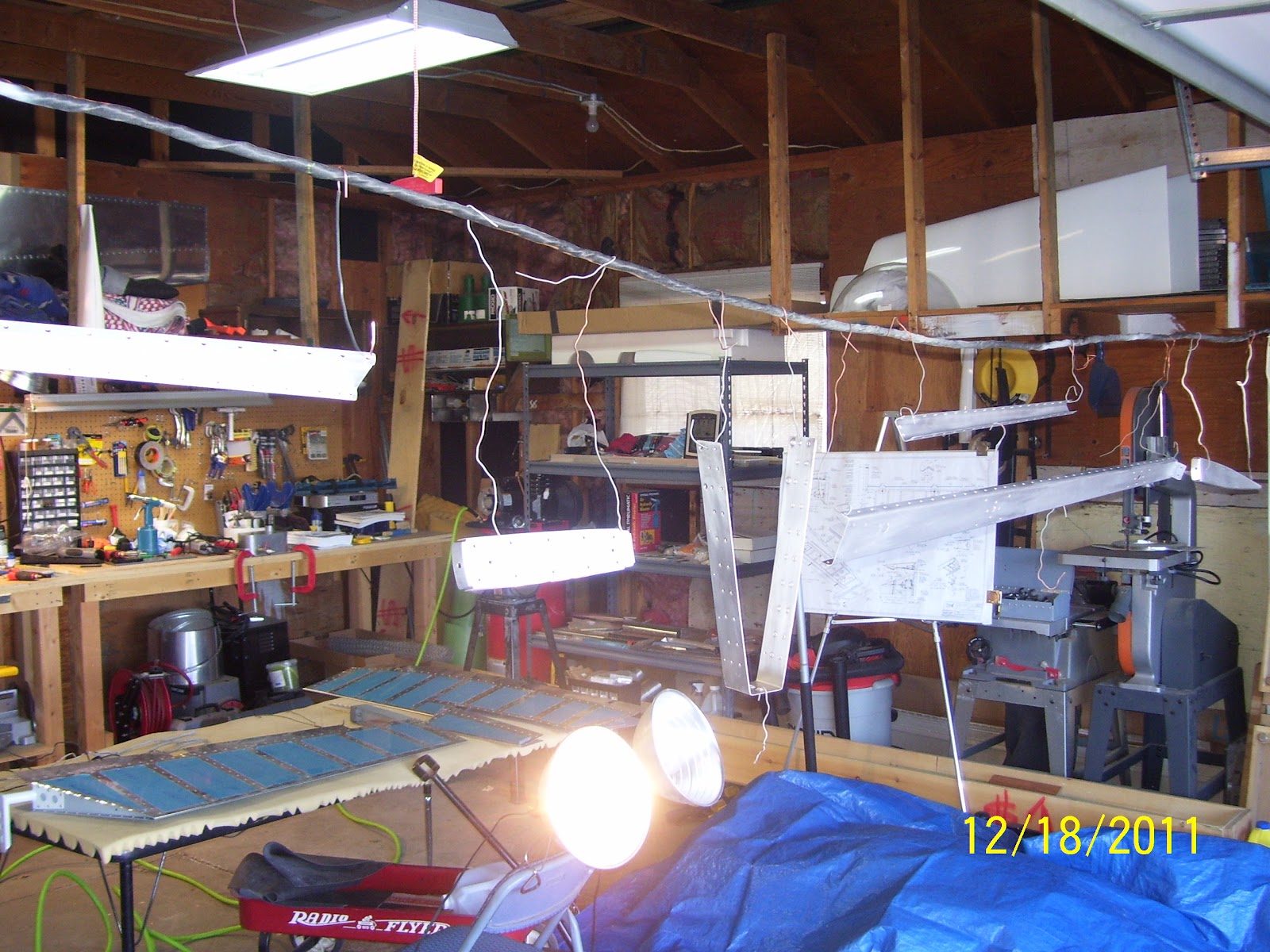
Next is a more close up pic of yeat another attempt to instroduce an adequate amount of light to one side of the parts that are strung up on my priming wire. My garage lights are closest to the work benches, and I string the wire up on the opposite end for ventilation and to prevent priming other things not intended to be primed, but I then suffer a penalty for lack of light on this area. The problem is that I get great sun light from the open garage door, so I can see that side of the parts very well, but I get shadows and severe lack of good light on the other side. So I tool part of the wing jig, mounted two of my High intensity reflector lights to the angle, and that seemed to work OK.


And finally the crappy rivet on the top that has set me back yet again. I can't even begin to tell you how sick and tired I am of trying to buck rivets in all these teeny tiny places. You do everything absolutely correctly to get to this point, and then it all goes to shit in a heart beat. Really sick and tired of this. Oh well, get new parts and try it again.


Followed by the crappy pic of the other side of both rivets. Really really bad.......No chance to salvage this - they had to come out, which lead to the distortion and final demise of the spar web in addition to the rib flange. If your shop heads end up looking like this, then they need to come out - no question.


Another one of the shop heads. Here is where is starts to get strange. It's hard to see in the pick, but if you look at the top rivet head, and then notice the bottom rivet head appearing at a slightly different ange than the one on the top, this is how the rivet shafts were sitting in the metal before I even began riveting them. They were obviously at different angles to each other, implying that something was wrong with the spar web or spar flange, or both. I noted that the manufactured heads on both rivets were not sitting at the same angle either. I ahve no idea why or how this section of the spar would ahve become so messed up, other than this possibly happening at the factory when they were forming the part on the bending break. It would not be the first time I received a badly formed part from the mothership, and probably won't be the last. Of course, it's much easier to blame them than it is to blame me, right?

And here is the setup I used - same as I did for the right side.

For whatever the reason, I decided to go ahead and set the two rivets that attach the tip rib to the E702 spar flange which is 90 degrees opposed to the other flange that attaches the counterbalance rib to the spar. Those were set with the pneumatic squeezer using the flange yoke without any problems. Unfortunately they will have to come out since the spar is now damaged from the failed attempts to drill  out and re-set the rivets for the counterbalance rib. I was so disgusted at this point I just decided to order all the tip ribs and a brand new spar:


And the final pic that shows just how messed up the fit of the two ribs is against the spar. None of the flanges are lying flat against the spar or the ribs. This was totally messed up and I am still at a loss as to the reason why. The counterbalance rib flange was bent while trying to move it out of the way to drive the rivets with the double offset rivet set, so I can explain that one, but the fit of the tip rib flange to the spar is also messed up.That one I cannot explain. Hopefully the next post will be a better one.....