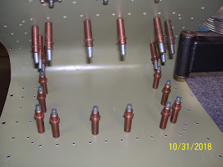
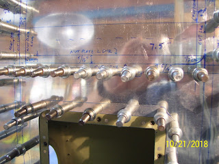
Thursday, November 8, 2018

Subskin Nutplate Rive Holes Part 2

I continued to clamp and drill the nutplate rivet holes for all 14 fuel tank attach nutplates using the methods shown in the previous post. Once those were done I decided to mark and drill the #40 nutplate rivet holes along both edges in the subskin that will be used to attach the removable outer skin to the subskin. I used a different method for these holes by taking a nutplate and inserting a #30 cleco in the center screw hole to secure it to the skin. I had to use this method instead of the nut plate jig because I am not ready to increase the size of the screw holes with the #19 drill just yet. So this was the only option for locating and drilling the rivet holes for each of these nut plates.

The problem with it is that you end up using the nutplate rivet holes to match drill the $40 holes in the skin, and that cleco does not exactly tightly secure the nutplate to the skin, so it is possible for the nutplate to shift a bit when drilling the rivet holes. How do I know that? You will see in a bit...….

Step 1 was to use a sharpee and a straight edge to draw lines next to each #30 hole that I had already drilled so that I had a reference line to align each nutplate. At the end of the day it does not matter too much if the rivet holes are all nicely aligned with each other, as long as the center screw hole is aligned properly. However, it does look better if the rivet holes are aligned with each other.

IN this pic I had already drilled the holes after adding the lines, but you can see how it looked.
Each nut plate was mounted on the outside of the skin, and the #30 clecoes were inserted from the other side as shown here:
I thought  had snapped some pics when I started match drilling the #40 rivet holes through each nut plate, but apparently I did not. How I did that was to align each nut plate with the lines that I drew so that the rivet holes would align  properly, and I simply held each nut plate with my fingers on my left hand while I drilled the holes through each nut plate with my right. As you will notice, this lack of securing the work properly ended up causing the drill to slip when I got to the most forward nut plates along each edge.
You can see how "off" the rivet holes are from the line that was drawn. At the end of the day this will not affect anything, but it really pissed me off when the drill slipped.After drilling the first hole I put a #40 cleco in from the top side, and then drilled the second hole.

When all the rivet holes were drilled it looked like this:
After these holes were drilled I removed all the clecoes and the nut plates and deburred all the new holes. Then it was time to mark and drill the holes along the rear area of the removable section of the subskin. I basically used the same process for these holes that I did along bot sides:

I had to get creative once again about how to clamp everything down so that each of the holes was being drilled into a piece of wood underneath the metal:

Here is a series of pics showing the clamping arrangement of the other side of the fuel tank attach nut plate holes. The wood and clamps had to be repositioned each time to drill each hole, and yes, it was just as much of a pain in the ass as it was for the other side:


After that was done it was time to dimple the #8 screw holes in the center of each nut plate position o the skin for all the fuel tank attach nut plates along one edge of the subskin. This time I made sure that the male AND female dimple die were installed on the C-Frame. The C-frame was used instead of a squeezer because the dimple are much crisper. I have seen many airplanes where the builder obviously used a squeezer instead of a C-frame to dimple these holes, and there is a very noticeable difference. ALL the screw holes had been deburred long ago, but I went over then one more time to be sure, because this is a step where cracks can form in the dimple. I read one post from a builder's kit log where he was using a squeezer and he ended up ordering new skins and parts because his dimples kept cracking. Had he used a C-frame he might have had those problems.

Here is the photo sequence:


The most forward holes closest to the bend in the skin were tricky to dimple. I basically used my head, hands, and whatever else I could to try to straighten the skinor at least orient it with the bend as it sat on the male dimple die so that the dimple would be properly oriented with the bend. I think this came out OK.
Next I needed to dimple the #40 rivet holes for each of the fuel tank attach nutplates. I did these with my pneumatic rivet squeezer. Once the skin dimples were done I now needed to dimple the #40 rivet holes in each nut plate so that it will sit flush with the dimpled skin. I should also back up a bit to note that prior to dimpling the fule tank attach rivet holes I did quite a bit of research on other build sites and on VAF, and ultimately called Vans, to find out if I should dimple those holes and use normal sized rivets for each nut plate, or if it was acceptable to use the NAS 1097 "oops" rivets with a smaller head so I could countersink the subskin holes instead of dimpling. The reason for using the NAS method s to avoid having to dimple the nut plate flanges by countersinking the skin.

I had seen builders do it both ways, but I wanted to be sure, since this is a potentially structural area of the aircraft where several parts of the wing are under stress. The general rule is that in that case you should dimple the holes and nut plates, because a dimpled hole is stronger than a countersunk one. Vans ended up telling me to dimple the holes and also dimple the nut plate holes using a squeezer.The problem with that is that the plans do show to use an AN426 rivet, but they do not show the dimple, which implies that the joiner plate is countersunk. They also state to use an AN426AD3-3.5 rivet, which is probably correct for a countersunk hole, but according to my rivet gauge the correct size rivet to use for a dimpled hole is an AN426AD3-4 rivet, so that is what I used.

Now, the problem with having to dimple the K1100-8 nut plate rivet holes, is that the center screw hole is already countersunk, so the area of the nut plate around he center expands outward quite a bit toward the rivet holes. If you use a standard sized #40 dimple die the female die is too wide for the nut plate center hole, and you will damage or deform the nut plate or mis-align the dimple in the #40 rivet holes. SO the solution for this is to use a reduced radius female die, or you can take a standard sized die and grind down one side so that it clears the countersunk center hole of the nut plate and cleanly dimples the #40 rivet holes on either side.Here it is installed in my squeezer:
Notice how the female die on the right has a smaller radius than the male die on the left.This allows you to dimple the flanges of the nut plates without damaging or deforming the center hole. I'll continue with more pics and info about this process tomorrow. Tonight I actually got tote point where I started setting rivets for the nutplates, and I had not set any rivets for quite a while, so that was refreshing. Eventually I will get the blog caught up with my actual progress, but my focus right now is to stay on track to finish all the remaining steps necessary to complete this mod. The closer I get to that point the more I want to finish it. Anyway, more later.


Wednesday, November 7, 2018

Drilling Nutplate Rivet holes for the Fuel Tank Attach Bracket Section of the Subskin

As stated in the previous post, I had some options for how I was going to locate and drill the #40 nutplate rivet attach holes. These are the 14 nut plates - 7 on top and 7 on the bottom, that allow screws to be used to join the inboard LE to the outboard fuel tank skin when they are butted up next to each other on the wing spar to make one contiguous leading edge. All of these holes are on one side of the subskin. I had purchased a #8 nut plate jig long ago but had not really used it just yet. So I decided to give it try.

The way that it works is that you must have already located and drilled and deburred the center screw hole with a #19 drill bit first, and then use the jig to start locating the two remaining #40 rivet holes for the rivets that attach the nutplate to the skin. Using the jig properly requires some planning. You basically need to be able to position the part so that there is clearance for the nutplate jig, and the real trick is that you are supposed to drill each of the two rivet holes into a piece of wood to minimize the burs that occur on the opposite side of the hole. The problem with this is that the jig has a center lug the same size of the #19 center screw hole that inserts into the drilled hole in the skin, and it becomes a bit awkward to try and hold the jig in position and position the drill to drill the holes. IN short, I fond this to be a rather monumental clamping effort that required some creative thinking.

I started by placing the subskin on top of two 3/4 inch drill boards on my bench to give it enough height to clear the tools. I drilled each hole on the inside edge of the subskin for starters, and started at the rear of the subskin since this is where I had the most clearance for the drill and the clamps. I changed this setup as I got closer to the forward edge of the subskin where space for the drill is almost non-existant. Here is the pic that does a much better job of showing how I set up for this:

This pic also shows two thin strips of 3/4 inch partical bard along the edge of the bench, shown toward the bottom right of the above pic. And then the nutplate jig is inserted into the first hole in the subskin, and I used a small metal clamp to secure the nutlplate jig to the subskin to keep it from moving as I drilled the rivet holes. The jig has this long handle on it that frankly causes the jig to be heavy on the end and this causes the jig to tilt upward just a bit in the screw hole. If left in this position then your #40 drilled holes might end up off center and out of position with the screw hole. So, as I have stated many times before - rule #1 is SECURE THE WORK!!!!! You want to set this all up so that NOTHING moves and you can keep your hands as free as possible for other tasks while drilling each new hole through the jig.

Here are some blurry pics and some good pics of the nutplate drill jig on both sides. On one side you get the #19 lug only, and on the other side is another #19 lug plus another #40 lug, which you use after you have drilled the first hole. The trick is that as long as you have the drill jig aligned properly for your fist hole, then it will all come out pretty nice. 

Getting ready to drill the first rivet hole:
The single lug side of the jig is inserted into the screw hole and the jig is clamped into position using the skin edge as a reference to ensure that holes are drilled as straight as possible along that edge. The small pieces of wood are inserted under the skin in the area where the new hole is to be drilled, which is through the hole in the jig located closest to the yellow clamp face.Whe you drill this first hole, you flip the tool over and insert both lugs into their respective holes and drill the rivet hole on the other side.

A view from underneath showing how the small wood drill board is positioned under the skin:
Here the first set of rivet holes has been drilled for the first hole, and now the jig is in position to drill the second rivet hole for the second screw hole. The first rivet hole has already been drilled:
I had to keep switching the position of the small clamp from one side to the other as I switched the jig position, because the drill board wood also had to be repositioned each time as well - a major pain in the ass. This is the main reason why a job that you might think will only take a few minutes to perform can actually take a couple of hours.


The handle on this ool just keeps getting in my way and makes this process more difficult, but I am hesitant to remove it because I am sure it may come in handy later on.
As I got down to the most forward holes of the subskin, the tool clearance for the drill became an issue, so I flipped the subskin over and drilled the final two sets of holes from the outer surface of the skin:
The real challenge was trying to use the jig to position and drill the most-forward hole, because this hole is located on the curved portion of the subskin where it forms the curved tip of the leading edge. My method for this also followed some advice I got from Vans a long time ago about this very problem where I was told that I could either bend the tabs of the nut plate to confirm with the curvature of the skin, or flatten the skin as much as possible and drill the rivet holes normally, and then allow the parts to confirm the nutplate as the parts are joined together later. I chose the latter method and attempted as best I could to flatten out the skin so that the rivet hole locations still matched the holes in each nut plate.

IN the pic above you can see the gap between the nut plate and the subskin. The theory is that when I finally get around to securing the fuel tank to the LE with the screws, the nut plate flanges will bend to confirm the curvature of the skins that are being attached together with the screw. I hope that works, but I won't know for certain until I get to that step. I might be able to take the nutplates for these locations and use the inner circumference of a steel tube and a clam to pre-form the flanges of the nut plate to the desired curvature. Will have to experiment with that and see how it goes.

Here is a pic that shows the truly creative nature of this process. I came up with a plan to use clamps and a heavy can full of clecoes to help flatten out the skin as much as possible before I drilled the rivet holes using the jig. The can opens up the top side of the skin, while the bench clamps pull the skin down onto the work bench and drill boards, and then one last clamp is cleverly used to pull the curved skin out to help flatten it in the localized area where the holes need to be drilled. This actually seemed to work quite well.


To that end, I have to rant just a bit now. I watched a series of videos on the EAA web site and other sites that supposedly show you how to use the nut plate jig tool. The problem with most of these videos is that they are only designed to show a demonstration, and almost always do apply the "real life" situation by using an actual part where all the holes MUST be aligned perfectly for edge distance and other considerations. SO they just apply the jig any old way to the test part and start drilling holes. SO they do show you how the tool is supposed to used, but they don't do a very good job of showing you how you need to use it in a REAL application. It basically boils down to the fact that they do not tell you or show you how you must align the tool properly so that all your rivet holes are in the desired line along the part, and they do not discuss how you need to position and secure the tool so that the alignment is maintained as you drill. I have found that I really hate that about many of the how to videos, because most of them are like - look, in just 5 minutes you do all this and you are done, when that could not be further from the truth in most cases. In reality the steps to position the work, clamp I down, figure the flow of the work, etc. take consider planning and thought if you want to do it correctly.

I have more pics to post about this process but will finish later as it is late now. I am also  a lot further ahead than this step but will finish posting each step in the process so that everything I have had to do to finish this up is properly documented. Till then, KPR....

Friday, November 2, 2018

Finished Dimpling the Remaining Perimeter Skin to Subskin #40 Rivet Holes

Last night I finished dimpling the remaining #40 rivet holes that will attach the outer LE skin to the subskin around the edge perimeter of the removable skin section.  There were some holes in the LE skin and the subskin that I could not reach with the pneumatic squeezer, so those would need to be completed with the C-Frame tool. First I completed all the #40 holes in the subskin, and then I completed the remaining holes in the LE skin.

To do the LE skin, I have to move even more stuff on the workbench out of the way, because all of these remaining rivet holes are on the inboard edge of the skin. This means that the rest of the skin will be hanging off the edge of the table to some extent, and so I had to ensure that there was clearance for that. It was also a trick to get the LE skin from the cradle over to the dimpling table. I needed to remove all clecoes from the LE ribs, mark them for their position I sequence so I don't screw up the location like I have done once before. After the ribs were removed I removed the skin from the cradle and careful moved it over to the dimpling table. Then I ponded out the remaining #40 holes in the top and bottom of the LE skin and placed it back in the cradle. DONE with that step!

Then I had to put some thought into how and when to locate and drill the #40 rivet holes for the nutplates. I was having some difficulty trying to remember if I should use the screw inserted method or the nut plate jig method to drill these holes in the subskin. to avoid the confusion, I had to separate how I was thinking about the Fuel Tank attach holes on the inboard edge of the subskin, from the nutplate holes for the removable section of the LE. The tank attach holes have already been drilled to #19 and are ready for the drilling of the #40 holes for those K1100-8 nut plates. The other nut plate locations for securing the removable section are still only drilled to #30.

For the tank attach nut plates, my dilemma was trying to determine if I should dimple the # 19 screw hole first, and then position the nut plate over the dimpled hole to drill out the #40 nut plate rivet attach holes, or if I should NOT dimple that hole and apply a different technique to locate and drill the #40 holes first, BEFORE I dimple the screw hole.

For the other nut plate holes the decision was a bit easier, because those screw holes have not been enlarged yet, and so I can't dimple those at all just yet for reasons stated in previous posts. A review of my Sept 2017 posts when I did the nutplates for the access panel in the subskin revealed that the #40 rivet holes should be drilled BEFORE the screw hole is dimpled. So my plan for both sets of nut plates is this

Tank Attach nut plates: Use my nutplate jig for K1100-8 nut plates to locate and drill the #40 rivet holes for each of those nut plates.

Removable LE skin nutplates: Us the #30 clecos as I did in the previous post to position the nutplate onto the subskin, and then match drill the #40 rivet holes through the holes in each nut plate.

SO I will be using two different methods to locate and drill the #40 rivet holes for these nut plates, due to the differences in the sizes of the screw holes in each of these sections of the subskin. No pics tonight - I'll do this work tomorrow when I am fresh and awake. This is no time to screw things up now. I'll repeat that same statement when I am finally ready to cut out the section of the LE skin. Still plenty of opportunity to completely mess this up if I am not careful.

Wednesday, October 31, 2018

Dimpled the New #40 holes in the LE Skin and Subskin, Fitted Nutplates on Subskin

Last night it snowed and got cold, so I did not do much on the airplane except make plans for what I would do today. The next step was to dimple the new #40 holes surrounding the removable section in both the outer LE skin and the subskin. I used my C-Frame tool for most of the subskin holes, and the pneumatic squeezer for the rest of them. Then I was able to use the squeezer on many of the #40 holes in the outer LE skin, but there are still several that will require me to use the C-Frame tool to reach those. I have a little too much clutter on the bench and it was starting to get cold again, so I called it quits for tonight at that point.

I did, however, cleco the K1100-8 nut plates onto the subskin so that could check the fit and position. I used a trick that I learned while fitting the fuel tank, where you can use a #30 clecoe through the #30 holes I drilled for each screw location, and the clecoe will just fit through the hole in the K1100 nutplate and secure it to the skin so that you can drill out the #40 holes for each of the two rivets used to attach the nutplate to the skin. I put each cleco on  the inside of the subskin through each nut plate on the outer surface and adjusted the position of each one to check the initial fit and alignment. Here are the pics:


I'll need to clear off the bench and dimple table so I can take the LE skin and finish the remaining dimples on the perimeter skin #40 holes for the rivets, then drill the nut plate #40 rivet attach holes (2 per nut plate) in the subskin and deburr them, then figure out if I am going to dimple or countersink those #40 rivet attach holes for the nut plates, and proceed with that decision. Then comes cutting the metal out of the LE skin, making the edges nice and straight and smooth (except for the rounded 1/2 inch radiused corners), making the file folder template, marking screw hole locations on the new file folder template, fabricating the new removable section of the skin from .025 2024-T3 alclad aluminum-same as the LE skin (will probably make several "blanks" for this), match drill the #30 screw holes in the subskin and the removable section up to #19 for the #8 screws, deburring those holes, dimpling them for a #8 AN509-8R8 screw, and riveting the nut plates to the underside of the subskin. And then, after all that is done, I finally get to re-assemble and rivet all the LE parts together, and mount that damn thing permanently to the Left wing. 

Yup, I can't lie, I'm just about out of patience with all the LE work I've had to do for this mod, but the truth is, this is just the beginning. I still have other fabrication work to do, not to mention a repeat of everything I have done up to this point for the right wing LE. But at least the work that remains to be done after the major metal work is finished will be the "fun" part of the reason why I started this mod in the first place. The delays resulting from all the "unknowns" when I started this mod will not exist for the right wing, since I supposedly now know how to do everything and the order in which to do it. And for the right wing LE I will not incur the delays that were caused by the stupid pre-cut access panel in the bottom of the left wing LE skin either. So things should go a bit quicker for the right wing LE mod - I hope!


Tuesday, October 30, 2018

Marked and Drilled Corner Rivet Holes, Removed and Disassembled the LE and Deburred the Holes

I was really stressing over the position of the nut plate screw holes, and then, after all the measuring, marking, research, and second guessing everything, I suddenly realized something. The removable section of the skin is not really going to be all that "stressed" when compared to the rest of the outer skin. the subskin underneath is what is designed to handle the loads imposed over that portion of the LE. The removable section is just going to be a curved piece of aluminum that basically form fits over the subskin. There will still be some loads imposed by tension and compression due to aerodynamic forces of the air flowing over that section of the LE, and these loads will fluctuate based on the G-loading that is placed on the wing curing certain maneuvers, but again, the subskin is what is going to absorb the vast majority of these loads.

Because of this, I really do not need to fret so much over the location of the screw holes. That said, I had settled on 3 along each side and 4 along the rear edge to ensure that everything is held down firmly so that the removable section still aligns with the rest of the LE skin when it is screwed in place.

From my previous post, I also knew that I had to reposition the rear corner screw hole so that it was not placed directly in each corner, but placed on either side of the corner. One other thing that was causing me pain was that I was trying to prevent additional stress points by maintaining the existing rivet pattern as much as possible. As such, I was trying to maintain a line of screw holes along each side that would align the screw holes I had already drilled for the nutplates that will attach the fuel tank skin to the LE skin when the two sections are joined together. While this would hve almost worked well for the bottom side of the LE, this was not going to work all that well on the tops side of the LE, since the screw hole patterns differ just a bit on the top and bottom sides of the LE.So I decided to use the most-forward screw hole of the joiner plate area to align the most forward nut plates of the removable section as a starting point, and I chose to move the rear-most nutplate center hole 3/8 of an inch forward from the corners where the nutplate lines from the sides and the rear intersect each other. Then I decided to move the rear-most corner screw hole locations inboard about 3/4 of an inch from that same intersecting corner. This created the desired effect of offsetting the rear and side nut plates in each corner so that the screw holes would be on either side of the actual corner, but close enough that they should lock down the corners of the removable section with no problem.

Here is a close up one of the corners after measuring and drawing the approximate location of the nutplate by positioning it over the mark for the hole and tracing the outline of the nut plate so you can see what I am rambling about.
As you can see this provides plenty of clearance between each nut plate. Do  not get confused by the drawing of the side nut plate where the end appears to be right over the corner again. You have to remember that the nut plates will actually be installed on the inside of the subskin to accept the screws from the outer skin. They are drawn here so that I know how they will be oriented on the subskin when I install them.

The next thing to resolve was the spacing between each of the nutplates along each side  and the rear of the removable section on both top and bottom of the LE. As I previously mentioned, for the sides I chose the location for the most forward and most rearward nut plates, and then I more or less decided to split the difference of the distance between each of those locations for the location of the nutplate in the middle.

For the rear-most nutplates, after setting the two corner ones 3/4 of an inch inward from the intersection of the two nut plate lines, I then used a distance of 2 inches from each rear corner nutplate hole to position the next two inboard rear nut plates, and that left whatever distance in the middle, which was about 1 5/8 inches or so between those two nut plates. These distances are within the same distances where other similar nutplates are installed on the plane, so I feel pretty comfortable with the locations that I came up with. 

here is the pic that shows how I aligned the forward-most nut plate holes with the existing holes in the joiner plate:
And here is a shot of the spacing between the rear-most nut plates, flipped 90 degrees the wrong way for some stupid reason:

Next is a shot of how the perimeter rivet holes for the skin and the nutplate screw hole locations looked after they were drilled with a #40 drill bit for starters . I once again used a center punch to mark each hole, and manually turned the #40 drill bit to start each hole before finishing it with the drill under its own power:

After all the perimeter and nut plate holes were drilled to #40, I then switched to a #30 drill bit to enlarge the holes for the nut plates, since the screw holes ultimately need to be drilled to #19 to accept the #8 screw. Here is a shot showing the clecoes in each of the enlarged holes for each nut plate. Unfortunately it came out blurry for some reason and I could not correct it.
Tonight I had made my decision about the gap in the corner for the outer perimeter rivets. I decided to do exactly as I stated in my previous post where I would add one more rivet to each corner but back it up just a bit so that the edge distance was consistent with each rivet on either side. SO I drew a line to bisect the 5/16 x 5/16 square that includes the rear-most corner, and then I took a ruler and measured along that line, and used the edge of the curved corner of the removable section that intersects with that line to measure another 5/16ths of an inch from that point outward, and marked that location for the rivet hole. The net affect of this is that it provides a rivet line with the same rounded contour of the removable skin, which is something I have also seen done in other areas of the build.

Here is the pic after the new corner holes were drilled to fill the gap:
And here is the entre bottom section with all the holes drilled and clecoed. From this you can start to get a better idea of what I am trying to do:
And another blurry one of the top side of the LE
With those holes done I was ALMOST ready to go ahead and enlarge the nutplate screw holes to their final size using a #19 drill bit. It was a good thing that I decided not to do that just yet. Just as has happened to me about a million times in the past, I started to think about the next steps after this was all done, and that major next step is to disassemble the LE and subskin and finally cut out the LE skin along the cut line marks and clean up the edges so they will accept the .025 removable skin that I would still need to fabricate. As  I thought through this process it dawned on me that I would still need to figure out how to mark and drill the same screw holes in the new part. Unfortunately it looked like I was going to need to try to do this from the inside of the subskin, because the new removable skin would have to be fabricated from a new piece of aluminum, since the skin on the LE would be cut away and not really viable any longer - or so I thought. 

Then, after thinking about it today, I realized that I can resort to a trick I have used before, by taking a file folder and cutting it to size to match the dimensions of the cutout section of the LE after I finish trimming it away. Then I can also use either the cut out section of the outer LE skin, or even the subskin holes to locate and drill the nutplate hole locations in the new file folder template. Then I can drill them out on the template and use it to outline the new removable section on a piece of .025 2024-T3 aluminum, match drill at least the first set of nut plate holes on the bottom side to start, and begin the process of form fitting the new part to the LE by attaching the bottom and wrapping it around the front of the LE to ensure that it is tight against the subskin, attaching the screws as I go.

SO, I can use the file folder template to ensure that I put the holes in the correct location on the new part that I must fabricate. I may have mentioned before that this part of the process is very similar to what one does when they place a landing light in the outboard section of the front of the LE. The only real difference is that the templates from most landing light kits for RVs are already created and so you just have to use the marks on the template that is provided. IN my case I am te one that has to create the entire template - just oodles and oodles of fun.

So the hole point of this ramble is that I should NOT enlarge the nutplate holes any further until the LE skin section is removed, and new part is fabricated so that I can match drill the removeable section and the subskin at the same time when I am finally ready to do that. SO those holes will remain sized to #30.

SO the next steps were to remove the LE assembly from the wing, remove the clecoes attaching the subskin, and debur all the new holes, and then dimple the outer perimeter rivet holes in the subskin and the outer LE skin. Then I will be ready to cut out the section that is to be replaced by the removable skin. Frankly, after all this time, I cannot believe that I am even talking about this. Of course the sad part is that I have all of this same thing to do on the right wing, and the thought of that is a bit daunting right now, knowing how long  it has taken me to do this on the left wing. 

Anyway, some pics after the LE was removed and the holes were deburred:

And finally the bottom and top side of the subskin after it was removed from the LE and the new holes were deburred. At least the hole placement for everything seems to have come out pretty nice. Now I just have to hope that I do not screw up cutting the section out of the LE skin!


Sunday, October 28, 2018

Marked and Drilled the Remaining LE Skin Rivets for the LE Mod

It was last March when I had finally managed enough courage to mark and drill the additional inboard and outboard rivet holes that will secure the edges of the LE skin next to each rib flange. I left off at the point where I needed to determine the number of rivet holes to make and drill for rear-most rivet holes on the top and bottom sides of the LE.

I specifically left off with a bit of a dilemma, because I was not sure about the rear rivet hole placement in the corner. If I used the marks from the lines I had drawn for the rivet holes, then the rivet pitch (distance between rivets) between the corner rear rivet hole and the first edge rivet along the edge near the same corner was a little bit wider than it is supposed to be when setting a section of multiple lines or rows of rivets next to each other.

SO I made a decision to at least mark and drill rear corner rivets, realizing that if I needed to later I could always add one more rivet between that one and one along the side to fill the gap. Again, the goal here is to prevent having to reassemble and disassemble the entire LE yet again for a couple of lousy rivet holes. I want all the holes to be marked and drilled so that I only have to disassemble the LE one last time. It's time to finish this beast once and for all.

Step one for locating the rear-most rivet holes was to use my rivet fan by drilling the four marked rear corners (2 corners each for the top and bottom side of the LE skin) with a #40 drill, and then clecoing the edges of the fan to each corner hole. I started with the bottom of the LE because it is flatter than the top side and a bit easier to work with.
With both corners of the fan clecoed in place, I then took a #40 drill bit and manually turned it inside each of the holes of the now equally-spaced rivet fan to mark and start the drill bit in each of the holes to prevent the drill bit from slipping off target. Once that was done I removed the rivet fan to view my handy work:
Then  was able to finish drilling each of the new holes on the rear side. This next pic shows the left side corner and the amount of space between the rear corner rivet and the first side rivet, which is at least 7/8 of an inch I think. it also shows the intersecting lines where I could place one more rivet in between these two to fill the gap. The problem with using that mark is that it creates a situation where that rivet's edge distance to the curve of the removable skin it right on the allowed limit, and so if I do add another rivet to this location I will probably set it back from the corner just a bit to present more of a slightly rounded rivet pattern around each corner, which would match the contour of the removeable section of the skin. And of course it also shows the rear rivet holes all clecoed together.
 Here is another closeup of the other corner on the top skin. I should also note here that the original plan was to use the same distance between rivets to adhere to the same standard practices for making patches to LE surfaces by matching the same rivet spacing used where the LE skin attaches to the main wing spar, but I felt that using the rivet fan to locate the holes also just about matched this same spacing, and it made it much easier to ensure that I would have a row of equally spaced rivets along that line.
Working on the curved surfaces always has many challenges, and frankly I have found this to be the most difficult aspect of the build so far, especially as it pertains to this LE mod that I am doing. Here is  a much better shot of how I positioned the rivet fan on the top side of the LE skin, which of course is the most curved side.
And the full row of rear rivet holes drilled and clecoed on the bottom side:
With all the LE skin to subskin rivet holes marked and drilled around the perimeter of the removable skin section, now it was time to determine what screw size nut plate size, the number of each along each side and rear of the removeable section, and the spacing in between each one. This was the most frustrating part of the mod so far, because I am unable to find any written source of info whatsoever that contains a formula or rule of thumb to use to determine how many screws or bolts need to be used in a certain area. So I contacted my Technical counselor and he consulted with a certified A&P mechanic. Basically I was sited the same rules that are established for rivet spacing, so I did not find this to be particularly helpful. I know that aircraft screws and bolts each have very specific ratings in terms of tensil, shear, and torsion ratings, and each nut plate also has ratings for this, but the one missing link to all of this is that I do not know how much of these forces are being applied to the areas where they will be used on the LE. 

So my next best method was to look at several areas of the airplane where Van's is applying similar screws and nutplates, and copy the spacing as much as possible. I plan to use K1100-8 nut plates with AN509-8R8 screws to attach the removeable section. I noticed that in various areas of the kit Van's uses spacing for these nutplates and screws that is anywhere from 1 7/8 inches to 2.5 inches. Based on on that, I set out to determine how many nut plates and screws need to be along each inboard and outboard top edge, and how many should be applied to the rear edge. this next pic was a first attempt at laying these up, but later on this changed a bit, after my tech counselor confirmed a suspicion that I had that you should not try to attach nut plates or screws directly on a corner of any part. 

This is because the corners of anything are where the largest stress concentrations tend to occur, and so if you want things to start cracking just start putting fasteners directly on corners of various parts. Instead, you need to offset the fasteners so that they are on either side of the corner. IN the next post I'll show the corrected/new layup for the nut plates on both the top and bottom sides of the LE. There are about a million measurements involved in all this, which is also why I will address all that in a new, separate post. Bottom line is that I think I now have the layout determined for the screw holes on the top and bottom of the LE, and it amounts to about 20 of them (10 on the bottom and 10 on the top. The screw holes have to be drilled before I disassemble the LE for the last time, so that I can then drill the corresponding holes for the rivets that attach each nut plate to the subskin. I plan to drill these holes to #30 first, and then to #19. Once the LE is disassembled I will be able to finish drilling and sizing all the screw holes in the subskin, dimple them,  and FINALLY cut out the section of the LE skin. Almost there.....
And one last pic of the rivet fan on the top side of the LE. Notice how it is positioned differently that how it was on the bottom side. this is because of the difference in flatness on the bottom vs. the top of the LE: