Monday, February 6, 2012

442 hours - Look ma, no more clecoes!

I'll continue to take credit for even small milestones at the rate that I am going with the left elevator and trim tab. I managed to rivet the other half of the trim tab hinge to the top of the elevator, and managed to sink 6 pop rivets into the last riblet ( 3 on each side). Checked the alignment of the hinge pin and it still goes on with relative ease, which means that I did not bend any of the eyelets out of alignment while riveting the hinge on. All the pop rivets went on with relative ease - nice and flush. Then I decided to try to tackle drilling out the one pop rivet on the outboard side of the trim tab that was sitting just a bit too proud for my liking - remember, the one did not want to drill out a couple of days ago.

One thing I have learned about drilling out steel pop rivets - avoid it all costs! Anyway, more on that later. Here is the elevator with trim tab in position  - no more clecoes holding the hinges or the riblet - everything is riveted.

Next is a close up showing the pop rivets now holding the riblet on the elevator (left side of pic), and the gap required between the outboard edges of the elevator and trim tab (3/32")

I'll remove the sharpee marks on everything now that the trim tab installation is all but complete. That way it won't look like my gap line is way off the mark !

Next is a shot of the clean line on the top of the elevator with the trim tab in the neutral position. After all the careful measuring and re-measuring and trial fitting, sure is nice to see this come together. While it has taken me a long time to get to this point, I am still glad that I have only had to make one trim tab, while others that reach this step sometimes have to make two or three before they get it right.

And a nice rivet line of flush rivets attaching both halves of the trim tab hinge to their respective parts....

I used the hand squeezer again with the standard 3 inch yoke, with the small 1/8" x 3/8" wide flat set for the shop head (minimum interference with the hinge eyelets), and the 1/8" x 1/2" wide flat set on the other side - same way I did the hinge on the trim tab. I was still really concerned about not having enough clearance for some of the eyelets, since some of the rivet holes are directly behind an eyelet, but between the thckness of the two 1/8" thick flat sets, plus the gap required between the sets to create the proper shop head, you really don't have to worry about it too much. Just go slow and make certain you do not apply any undo pressure on any of the eyelets and it works out fine.

The hinge pin sticking out of the end is part of the temporary hinge pin they provide in the kit. You get the proper length hinge pin in the fuselage kit for some strange reason. The end of this pin still has to be bent and either safety wired to the E616PP trim tab spar on the elevator, or secured by using an eyelet taken off of a piece of hinge (I will probably do the latter). For now you just use the temprorary one to get it all lined up and installed.

Next is the fiasco with drilling out the pop rivet on the bottom of the trim tab. Truth be told, both of them were sitting a bit proud of the surface, but after all I went through just to drill out one of them, I am totally fine with leaving the other one completely as is. No matter what drill bit I tried to use, I could not get this rivet drilled out to save my life. And the standard method for solid rivets, which is to drill the head out and then snap the head off - Haaaa! Forget that. The rivet already has a hole in it from the mandrel going through the center of the pop rivet, so the edges are already shallow, and this is a hardened structural pop rivet that will not break away like the solid rivets do.

So the things I learned from posts on VAF if you ever have to do this are: take a small diameter punch and drive it lightly with a hammer through the existing hole oin the center of the rivet until the bottom (round part) of the mandrel comes out the other end, then take the drill and drill out the rivet.... simple - right? Not really.
I think I finally reasoned that I needed to use at least a 7/64 inch drill bit to drill out the rivet, because that is what I had to use to widen the original rivet hole for the pop rivet. You pretty much have to drill out this rivet by drilling through the sides without enlargening the hole. I ended up getting the head to lift out of the hole just enough to get a pair of small needle nose pliers on the head, and I tried crimping and twisting the flanges of the head off so I could then punch the remaining part of the rivet out of the hole. It ended up requiring the combination of drilling out the rivet with a larger drill bit (7/64"), and then prying off as much of the rivet head as I could, without damaging the trim tab skin, and drilling some more until I could put a punch in the hole and drive out the remaining portion of the rivet.

I finally got the dang thing out, and much to my surprise did not enlargen the hole too much, but it was still widended enough to cause me some initial concern about setting another pop rivet in the same hole. I decided to go ahead and try it again after trial fitting a new pop rivet in the hole, and I realized that all that work to get the rivet out actually deepened my dimple just enough to allow the rivet head to sit nice and flush in the skin. The rivet grabbed the riblet and the skin pretty much the same way that the first one did, so it turned out to be a nice tight fit. This next pic is the remnants of the pop rivet that I had to drill out. there is the round mandrel tip that had to be punched out, the rivet shaft, and a small piece of the rivet head that I managed to pry off with the needle nose pliers....

Moral: Avoid drilling out pop rivets if at all possible - the structural pop rivets are a pain in the ass to get out.Perhaps if I practice removing them I will get better at it. This whole process brought back very bad memories from working on the horizontal stabilizer and messing up rivet holes, requiring a major structural repair after the fact. Fortunately this experience turned much better than that one.

Next is a close up of the gap between the trim tab and the elevator.

And finally some pics showing the nice streamlined trailing edge one from the outboard side and the other from the inboard side of the elevator - still looks very nice, even after all that mussing and fussing and fiddling with the parts all this time....


Sunday, February 5, 2012

440 hours-Elevator riblet prep completed

Sure is fun trying to finish up a major airplane assembly when you are fighting a relapse of strep and endure the largest snowfall in the month of February that Denver has ever had. A 2.5 day storm dumped 20 inches of snow that left 3.5 foot snow drifts on my driveway. Finally had to put the snow blower to work..

Anyway, I managed to summon enought strength to do a little work on the bird tonight. Except for a touch up coat of primer, the riblet and the elevator skin rivet holes were drilled, dimpled, and prepped for the MK319BS pop rivets that will need to be used to attach it to the elevator.

I finally committed to marking and drilling the holes for the riblet. Marked the first hole wigh the center punch at the intersection of the sharpe lines I had drawn that mark the hole locations in the riblet (or so I hoped). I decided to simply work the drill bit by hand without running it with the compressor. It does not take long for the drill bit to penetrate the thin .020 aluminum skin of the elevator. I did it this way to verify that the holes were in fact lining up correctly with the riblet under the skin. Luckily this turned out to be a non-event. All the holes I drilled were pretty much spot on, and the riblet web aligns almost perfectly with the ends of the skin edges of the elevator.

Once the holes were drilled I needed to debure and dimple all of them. This requires 6 rivets - 3 on the top and 3 on the bottom, and uses the existing holes from the original practivce kit rib from which it was fabricated. I was able to use my standard dimple dies and 3 inch yoke in the squeezer to dimple the first hole closest to the spar edge of the elevator, but had to use the close quarter tool to get to the remaining four holes because the opening was not large enought to fit the yoke in side to set the dimples.

Here is one of the leading edge holes dimpled with the squeezer:

Then I had to get creative again. I needed to support the entire elevator in such a way that I could slide the skin over the close quarter dimple tool so I could slam the remaining dimples with the rivet gun. This setup required the use of a 2x4, clamps, and two chairs, one of which was replaced by my son who graciously came out to help me once again. In previous posts at the beginning of the left elevator build I needed to use some 2x4s to dimple several other holes in the skin. I used the same 2x4 adn had to place the close quarter tool on either side of it to provide the necessary clearance for the holes on both sides of the elevator skin. The 2x4 was needed to extend the tool out from the edge of the table far enough to clear the remaining portions of the elevator.


The last shot above shows the tool on one side of the 2x4. When I flipped the elevator over to dimple the holes on the other side I had to move the tool to the other side of the 2x4 to maintain clearance from the rest of the elevator, which tends to get in the way.

Riblet in place after all the holes in both the elevator and the riblet were dimpled:

All riblet holes on one side nicely dimpled.

This last pic is of the riblet after setting all the dimples and repositioning it inside the elevator. The holes need to be final drilled to 7/64" in order to fit the MK319BS pop rivets. Every time I have had to insert and remove the pre-primed riblet after setting the dimples, the primer tends to get scraped away from the riblet where the dimples are located. The parts tends to form a tight fit which locks into place once the dimples align with each other and the part slides into its final resting position. This makes it difficult to remove without marring up the primer a bit. So, I will put a fill coat of primer on this and then slide it into position for the last time, and then set the pop rivets. One step closer....

More snow in the forecast for tomorrow. Just another day in Colorado in the winter time......

Thursday, February 2, 2012

Picture catchup time since 1-18-12 - Trim tab and servo mount work

So last post I qrite bout everything I had done. Here are some pics to go with the post:

First shows the NAS 1097 oops rivets I used for the two rivets holding the lowest part of the trim servo mounting brackets. Since the flush head on these rivets is very small, it does not take much to countersink the hole with a deburring bit by hand. Notice one of the rivets already inserted in the hole.


Servo mounting brackets, cover plate, and elevator side of the trim tab hinge ready for primer:
Used some tape to mark the 3 5/8 inches of threaded rod that I needed to cut. Used the dremel cutoff wheel and grinder to smooth the ends. Clamped the rod between two blocks of wood to keep from damaging the threads.Took all of a split second to cut the rod.


And after the rod is trimmed and the other clevis is screwed on:


Next is after the mounting brackets are riveted to the cover plate. Shows the low side of the trim servo and really illustrates quite well the reason why you need to use the oops rivets on the low end so that the botom of the trim servo case will clear the rivets. Even with this setup, I will be curious to see how vibration and flight loads on the control surface impact this clearance. You will know if it is rubbing by checking for marks on the bottom of the servo case where the rivets are touching it. No marks is good,means that the clearance is adequate.


The entire trim servo assembly. The clecoes will be replaced when the time comes. In fact, I am thinking about replacing the screws for this with some torx head screws, because everyone says that the phillips head screws get damaged very easily

:

Next is fitting the inboard riblet. The web is inside so that solid rivets can be used. This process was a major pain the ass because I was trying to use some of the existing holes in the riblets and basically reverse-match drill the trim tab skin. A lot of careful measurements taken here before I started drilling holes. This riblet turned out pretty well.


And here is the riblet that goes into the outboard edge of the elevator. Notice the lines I have drawn through the center of each existing hole in the riblet, and the lines drawn after measuring the hole locations on the skin. Before getting to this step, you need to have already fitted the trim tab to the elevator, drilled all the hinge rivet holes on both sides, and filed down the edges to provide the required 3/32 inch clearance between the edges per the plans. Once you have done all that, you can fit the riblet on the elevator.


Another shot showing the nice side of the trim servo cover plate after the mounting brackets are riveted. You can see the 4 AN426AD3-3.5 rivets in the dimples (large heads) and the two AN1097 oops rivets (small head). Used my hand squeezer for these - just have to make sure you don't ding up the web of each mounting brackets. Trim down your yoke if you need to.

Next is the flat file I used to finish trimming up the edges of the elevator where the trim tab fits on the outboard end. Just had to do a little bit of filing to even up the edges. Everything looks nice and square.

And finally my latest acquisition of tools. Shown are 3 of the four wire strippers from craftsman professional tools, the 25 watt soldering iron, the slim line heat gun, and the box of assorted heat shrink tubing from GB products that I found at HD. I will be soldering a pigtail extension to the trim servo wires. Probably about 8-10 inches worth or more.


Funny - I am not even done with the empennage yet and I am already working on electrical stuff. One of the things you learn as you start to build the remaining structures of the airframe is that you really need to think about the build from the inside-out. This means having an idea about your wire layouts adn requirements, tubing lines, placement for landing, nav, and position lights, antennas, and so on and so on. The more you have this figured out ahead of time, the easier it will be to put everything in place during the framing process. The trim servo wires will need to exit the left elevator and make their way into the fuselage, and some sort of service plug or connector will need to be created so that it can be disconnected and serviced as necessary.

This last pic is of the outboard end of the trim tab, after I had measured, drilled and set the pop rivets for the riblet. UNfortunately the two rivets on the bottom side did not sit down very well in the dimples, so I tried to drill one of them out. I thought this would be easy, having drilled out other pop rivets on the rudder LE. Boy was I in for a surprise. I guess those pop rivets are not necessarily considered  to be structural, and so they are made of aluminum. The MK319 BS flush rivets are apparently much harder than aluminum, and even harder to drill out. I have never seen a drill use up two full tanks of air turning a drill bit and seeing absolutely nothing get drilled out before. Very wierd, and very troubling at the same time, since I don't know how the hell I am going to get this rivet out of the hole.


Anyway, I found some info on VAF about this. Looks like I need to punch out the remaining mandell head and then I am supposed to be able to drill the rivet out. We'll see houw that goes. Sure don't want to screw up the trim tab at this point, so I will take it slow and easy.

Big time snow expected here overnight and tomorrow. We'll see how much more I can get done over the weekend.....

Tuesday, January 31, 2012

438 hours - down ill for a week but back at it again

SO my last post was a week ago this past Saturday. On Sunday the 22nd I had another long day of airplane work done. Only problem was, by dinner time on that Sunday I was starting to feel like death warmed over. I very cold breeze was flowing right through me. I managed to make it to work on Monday but then everything really came crashing down. I went to bed immediately after getting home Monday evening, and went dtraight to bed, wearing all my work clothes AND my heavy winter coat under the covers just to stay warm, shivering like crazy with fever. Long story short, spent the rest of the week and home, was diagnosed with a really bad case of strep, got the antibiotics from the doc, and have been fighting to recover ever since. I am almost there, but it likes to hang on during these final stages and only give me small amounts of recovery each day, just to keep me in check I guess. Tonight was really the first time I have gotten back to airplane building since I fell ill.

Needless to say not much airplane work done, but got some things done:since my last post:
1. Researched and ordered a set of key hole wire strippers from Sears after finding out that the folks at the Ray Allen company are using them for their shop work on all the tiny 26 gauge tefzel wires they use to manufacture their trim servos. Unfortunately Sears would not sale the one stripper I needed by itself. It only came as a set with 3 other stripper tools. But at $45.00, compared to the $220.00 the Ideal automatic wire stripper was going to cost me, I decided it was worth the investment. The part number of the stripper is 73574, and is supposed to strip 22 to 32 AWG stranded wire. After practicing a bit, it still slices clean through about 4 of the 19 strands of wire in each conductor, but perhaps with some more practice I can prevent this from happening.

2. Finished priming adn installing the servo mounting brackets onto the cover plate for the trim tab servo. Used AN 1097 "Oops" rivets for the two rivets on the lowest side of the mounting brackets so that I would not have to dimple the cover plate and the mounting bracket holes which would have interfered with the bottom of the trim servo cover. This is a well known problem and the solution works great. Get the Oops rivet set from Avery Tools.

3. Cut my push rod for the trim servo according to my specs - about 3 and 5/8 inches. I think this will work out just about right. I cut the rod with the dremel cutoff wheel, then deburred the ends on the grinder so that the two stop nuts can be screwed onto the threaded rod. These will snug up under the base of each clevis to prevent the rod from turning, although this is such a snug assembly that I don't think here is much chance of that ever happening.

4. I have all but completed the trim tab, however I had two MK319-BS pop rivets on the bottom of the outboard edge that did not sit down in the dimples very well, and so I tried to drill one of them out tonight. I don't know what is going on, but I cannot drill this SOB'n thing out!. My drill bits just spin and do not remove any material. Now I need to find out what is going on and how to rememdy this little problem. Should have just left them alone.

5. I trimmed up the outboard edge of the elevator that sits next to the outboard edge of the trim tab. Vans wants a minimum of 3/32 inches clearance to prevent any possibility of binding, which is very wise. The problem is that there is about 1/32 inch of play in between each of the eyelets in the hinge, so you have to decide if you want 3/32 inches with the pay or without the play, and file the edges down accordingly. I decided to trim it without allowing for the play, so that means that with the play there is only about 1/16 inches of clearance. I will see what the tech counselors say when they come to visit. The problem is, until you get the trim tab and the trim servo installed for the last time, you can't know exactly how the hinge will position itself through the entire range of motion. Also, until you perform final trimming of the edges of the elevator, you cannot finish installing the last riblet. Everything depends on everything else. Makes you wonder how you ever move forward on this project sometimes.

Anyway, the edges are nice and straight. I must have messed up my initial measurements whne trying to determine where to cut the tabs off of the elevator a long time ago, because the gap on the bottom side was already pretty much where it needed to be, but I still needed to remove about another 3/32 of material from the top skin edge to get the proper clearance on that side. Careful use of the dremel tool and a file took care of that in almost no time at all.

6. The last thing I did tonight was to mark the hole locations on the elevator riblet and transfer them onto the elevator as best I could. Again, if I had it to do over again I would probably form my own riblets so that the flanges would have no predrilled holes in them at all, and then it would be a snap to drill the holes through both the skin AND the riblet, instead of trying to reverse-match drill the damn things so that the existing holes in each riblet can be used.

I bought a 25 watt soldering iron for the electrical wiring work, and also a small slender heat gun designed specifically for working with electronics wiring projects and heat shrink tubing in tight places. I think I can even fabricate a metal spout to attach to the existing one to ahve total control over the area to which the heat is applied, so that I do not risk damaging the plastic or other components of the switches or other things I will be installing.

Oh yeah also went to see the movie Red Tails with the RV Denver clan a week ago. That was fun and it was good to see most everybody again.

Anyway, no pics tonight cuz I am still in recovery, and I am too tried to upload all of them. Will try to do that tomorrow. PLan is to get the final riblet drilled, deburred, and riveted tomorrow, and then hopefully I can start working on rolling some leading edges.

Saturday, January 21, 2012

434 hours-Trim tab servo mounting bracket and cover plate - take 2

So I received the new cover plate from Van's and followed the same procedures in the previous posts to sraw a new center line on the cover plate that basically centers the output shaft of the servo arm with the center of the access hole in the plate and the elevator. In short, the line was moved barely an eighth of an inch or so from where it was.

Here I have attached the cover plate to the elevator and placed my straight edge/ruler over the slots where the center point is. I just roughly estimated where center was, and made a mark on both sides and drew the line.


Next I centered up the trim tab on the elevator and took my straight edge and extended it from the new line on the cover plate down to the control horn. Now you can see that the horn is displaced off to one side of the horn, just as I had expected.


Next is transferring the line from the top of the cover plate to the bottom. I also deburred and dimpled the cover plate, including the edges:


Not sure why this pic still appears to show that the arm is still a bit off center from the slot in the plate. It really was not. Anyway this gives you an idea of the clearance of the clevis pin to each side of the plate. In actuality it will be a bit different because there are two washers that are placed on both sides of the clevis pin during final assembly.


And here we are all clecoed together and clamped to the drawing for final positioning and drilling the mounting bracket holes to the cover plate.

Oh yeah, I did also draw another outline of the cover plate on my cardboard template. Here you can see the difference in the original line that I drew and the new one which is now centered with the slot on the plate. I did not notice the reflection on the bottom of this pic until just now. I was holding the card board against the top of the elevator skin. Amazing - even after all the finger prints and dings and scratches on the skin, it still acts like a mirror! So, just focus on the upper two thirds of the photo. Sorry for the illusion...

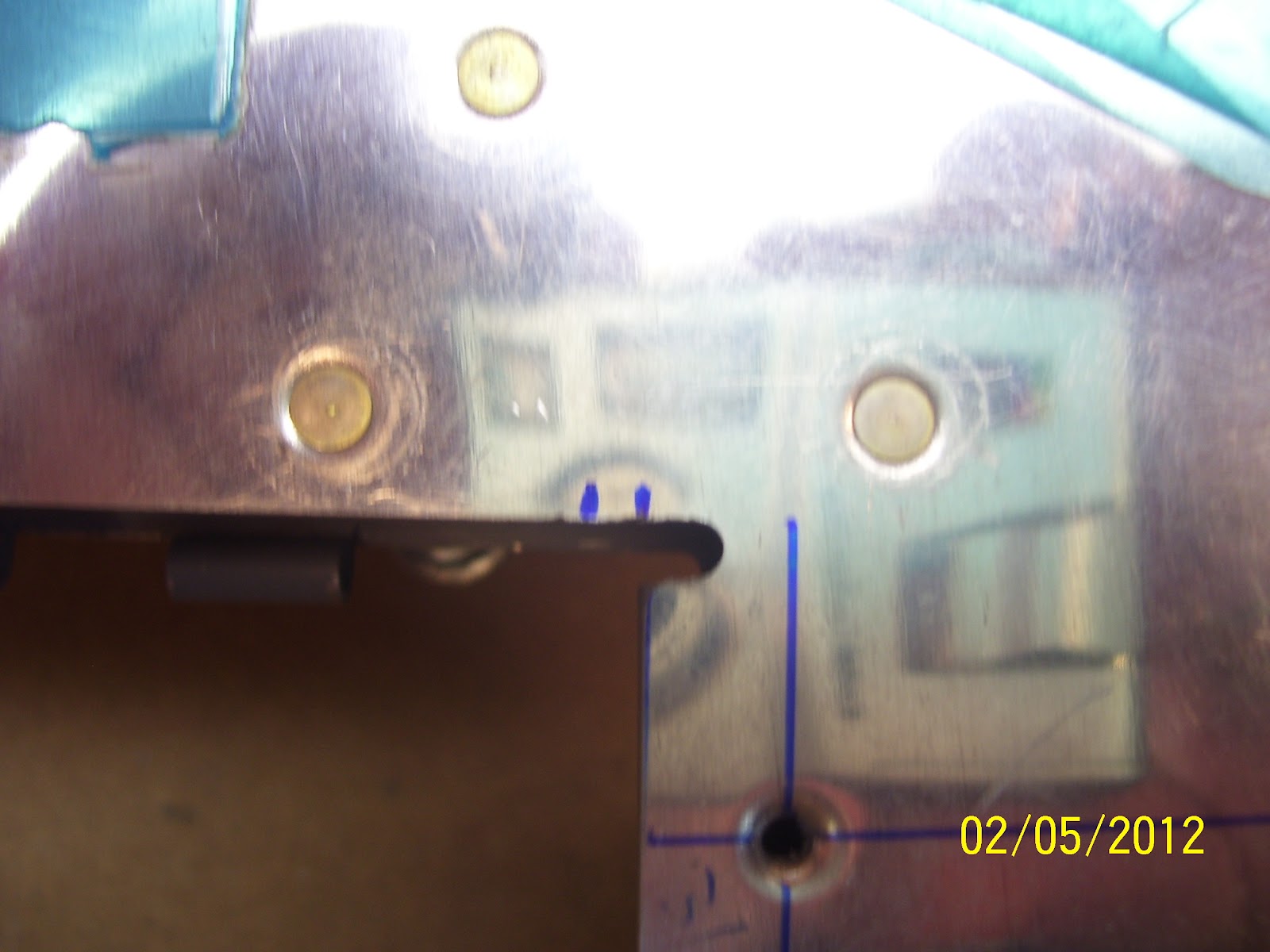
These next two shots attempt to show the clearance of the clevis and control arm of the servo against the cover plate when the arm is fully extended.

What this confirms is that even when the arm is fully extended there is still adequate clearance of the clevis pin and clevis with the cover plate. The only other concern at this point will be the clearance of the cotter pin that is inserted into the clevis pin to keep everything attached and secure.

Here are the mounting brackets  after removing the cardboard template, reclamped back onto the drill board. I once again traced the outline of the mounting brackets to ensure that they remain correctly aligned when I drill the rivet holes to #40 through the cover plate.


And here are the first 4 holes drilled and clecoed directly to the drill board. The last two holes extend beyond the drill board and I simply went ahead and drilled those as well in the overhanging position.

And finally checking the alignment of the threaded rod from the servo out to the control horn of the trim tab. Slightly off to one side, just as I had expected. What I have not shown is that I used Gorilla duct tape strips to hold the trim servo to the mounting brackets and keep the servo wires from getting crimped while I installed the servo in the elevator. There are screws and lock nuts to attach the trim servo to the mounting brackets, but those lock nuts are stiff as hell, and I did not want to permanently afix the servo to the mounting brackets just yet, so I used the tape.

The access hole, although appearing to be quite spacious when viewed by itself, is actually only just large enough to insert the cover plate-trim servo assembly into the elevator. You have to find the special method to twist and turn it just right so that it will fit into the hole. You also have to remember to position the servo arm so that it allows enough clearance to insert or remove the assembly. I found that centered works out pretty well. This is a note I will have to make in my maintenance procedures when I perform each annual condition inspection, or any time I need to service that part of the plane.

I don't know if others end up grinding down their nut plate flanges to align with the edges of the elevator skin around the access hole, but after fiddling with trying to get the servo inserted into the elevator, I don't see how you can get the mounted servo in there without doing exactly that. That is how closely matched the hole dimensions are to the cover plate assembly.

Pretty much centered through the hole, but what about the offset of the control horn? Now back to the great debate - bend the rod or don't bend the rod. So I called the Ray Allen company and spoke to one of Ray's sons that now runs the company. Had  a very nice conversation with him and learned that this company has it's roots from associations with Jim Kraft, maker of the Kraft radio control systems that were widely used in the 60s and 70s, right about the same time I was becoming interested in the hobby. In fact, my neighbor Kevin and his wife Mary stopped by while I was in the garage the other night to check on my progress. When Kevin saw the servo (he is also an RC enthusiast) his first comment was " gee, that looks just like a big RC servo." He is absolutely correct, but it is a heavy duty servo compared to the smaller ones that are designed for use in RC airplanes, but they all are basically designed to do the same thing.

Anyway. The main reason for the call was to detemine what to do with the Rod. I was told that he had looked at many many RV6s and other airplanes that had been out in the field for quite some time now, and he had never seens signs of the hole in the control horn warbeling or being worn away due to stresses of non alignment of the rod with the horn. Based on that, he said they don't recommend putting any bends in the rod, and his advise was just to mount everything up and check it, and then monitor it after the flying begins. I told him that I also noticed that the two part horn assembly tends to separate at the tip just a bit where the holes for the clevis pin are located, but when I apply force to the rod to move the trim tab it actually brings the horns closer together, which is good.

So maybe it will be fine "as is" with no bending of the rod. If you look closely at the plans from Vans, they also show the trim servo assembly with the one side of the wide clevis butted up tight to one side of the trim tab control horn. This leaves a very large gap of the other side of the clevis. I was always taught to aim for the mid point of anything that has any play to one side or the other, for reasons similar to learning how to land a plane on the center line of the runway. You keep it on the center line so that if anything should happen such as a blown tire, locked up brake, or gust of wind, or anything that might induce a side load to the object, you still have some margin of runway on either side of the center line to keep from running off the runway surface. Or in this case, from running into either edge of the control horn, which would create wear over time. Oh well - that's the way that Van's shows it in the plans, and with over 7500 of them flying out there, I guess I will follow suit.

In fact, he even asked me if the horn was still designed such that it is just two pieces of thin .020 aluminum connected together. I told him yes it was. He asked me because the width of the opening in the clevis that slides over both sides of the hole in the control horn is at least 3/8 inches wide, much wider than the thickness of the two control horn pieces. I was even wondering if we needed to insert a bearing of some sort to remove the gap, but I guess not.

Then we talked about the new trim tab assembly on the new Cessna Skycatcher, which is also apparently using one of their (Ray Allen) control assemblies. He commented about how beefy, ugly, and overbuilt that trim tab was. So I think it's kind of funny, on the one hand you have an overbuilt assembly for a production aircraft, and then on the other hand you have the "just good enough" approach that Van's is using. As long as there is no binding during movement of the tab, then it should be fine.

Here is a final pic of the rod as it exits the slot. Note the original mark on the top where the old rod centerline was located, compared to the centered location now. Whew, now that that is over, on to the next thing, which is to cut the rod to te proper length. SO this gave rise to another question to Ray Allen. How far do you screw in the rod to each clevis? He told me that the MINIMUM is only 3 turns on to each clevis. Apparently they have conducted tests where he told me that it took 400 pounds of pressure to separate the clevis from the rod with it attached by only three turns on each end. WOW! The trim servo itself is only designed to handle about 40 pounds of force. This means that inserting more thread into the clevis is a plus for strength.


In my RC days there was a standard practice to take the 1/16 inch threaded rods we use in the hobby and screw them all the way into the shaft of the nylon clevis, and add another 1/16 inch of threads as a safety factor and to allow for adjustments. This typically ended up being about 3/4 of an inch of thread inserted into the clevis. I can only manage to screw in the rod for this assembly about the same amount - about 3/4 inches, which is still way below the hole on the other end of the clevis. Apparently this is more than adequate enough. This also seems to be about the length shown in the plans from Vans, if you adjust for the scale of the drawing, which brings up another thing.

I searched long and hard on VAF to find posts that deal with the correct length to cut the rod, which is not mentioned anywhere in the plans. All you get is the drawing at 3/8 scale with no notes about this at all. This turns out to be a common practice with most of Vans full sized plans. Many drawings of subassemblies are set to 3/8 scale. I have found that there are many times that I want to determine the actual measurements from the scale drawings, and so in order to do this you have to know how to convert from smaller scale to actual size, and sometimes you need to go in reverse from actual size down to 3/8 or some other scale.

Anyway, after hours of searching I could not find anything that gave me the answers I was looking for. Some people made a reference to 3 3/8 inches, saying that this is what Vans recommends. But as I said, I could not find reference to that measurement anywhere in the plans. Finally I found one post with only two entries from 2007, and they basically said that they just estimated the length and cut it. Perhaps the plans were different back then, I don't know, but being an avid RC scale enthusiast for a long time, I was just not satisfied with the "esitmate and cut" approach to this. So I reopened this thread with a post that describes the detailed process to perform the mathematical conversion from the 3/8 scale drawing in the plans to reveal the approximate actual length of rod that should be cut. You can see my solution here.

'Nuff for now. Gonna go out with the rest of the Denver RV List crew to have dinner and see the new Red Tails movie tonight. Should be loads of fun. In the mean time, I have a 3 5/8 inch long piece of rod to cut, which is the length that I determined needs to be cut per the steps in the post. This leaves about 3/4 inches of rod in each clevis, and allows for the correct length between the servo arm and the control horn of the trim tab. Initial dry measurements of this length appear to be correct for my installation. Proof enough for me that the scale conversion method works, and takes the guess work out of the process.

Wednesday, January 11, 2012

431 hours - Measuring and drilling holes for trim servo mounting brackets

I ended up posting the last photo in my previous post out to VAF to solicit some responses about the offset lignment of the threaded rod as it runs from the attach point of the trim tab control horn down into the tapered opening in the elevator skin. See it here. It simply is about 1/8 of an inch too far over to one side. From VAF I received 3 options:
- Leave the rod straight and trim away material from the elevator skin, support bracket, and cover plate to make room for the output shaft of the trim servo and the rod
- Center the position of the trim servo and then joggle or bend the rod over as far as necessary to align it with the control horn
- Center the trim servo, leave the rod straight, and bend the control horn to align everything.

I decided that option 3 is just not an option. Bending the control horn presents all sorts of possible fatigue and failure scenarios as far as I am concerned that I just won't do it. This comes mainly from a lot of RC airplane building experience where bending a control horn to a point where it is out of alignment with the hinge line of the control surface causes fatigue to the horn, the clevis pin, and the clevis, and may also put strain on the servo or on the hinge of the trim tab.

Option 2 is what many people have done, but others warn that bending the threaded rod causes stress points in the rod where the threads are forced closer together, and this may lead to failure of the rod - also not a good outcome.

So I decided to explore option one a bit further. One comment I received from another builder hinted that you might not know just how centered or uncentered everything is without putting it all together, mounting it in the elevator, and checking it then. This was sound advice adn is the main reason I decided to proceed, even though I knew that te rod was off center from where I expected it to be.

The following pics describe a very handy process that I learned from Steve Riffe. It basically involves trsansfering the position of the rod as it aligns with the control horn onto the trim servo cover plate, and then making a template on a piece of cardboard or similar material that contains the outline of the cover plate, and an exended line for the pushrod location, using the line marked on the cover plate as a reference.

It starts by screwing the cover plate into position, attaching the rod and one clevis to the trom tab control horn, laying the rod over the access plate, adn drawing a line a cross the top. This is the reference line that shows the position of of the rod as it enters the area where the trim servo will be located. Use a stright edge to transfer the line from the rod to the access plate:


Next carry the marks for the end of the reference line on the top of of the cover plate down the edges and then draw the same line across the bottom of the cover plate.

Turn the cover plate over so that the bottom faces up. Take a piece of carboard or similar that is large enough to transfer the line for the rod, position the bottom of the cover plate about half way off of the edge the cardboard, and trace the outline of the plate into the cardboard. The reason for tracing only half of it and not the whole thing will become apparent a bit later. IN this next pic, I show the cardboard traces of the cover plate, one in its entirety and the other half way down. Also note the line that I have extended from the cover plate onto the cardboard for the rod location.


Clamp the cover plate over the tracing, again - bottom side up.


Next, cleco the trim servo to the left and right mounting brackets, measure the offset distance (3/8 of an inch from the rear of the plate, and draw that line on the plate. This is where the back edge of the mounting brackets should sit on the cover plate. Take the trim servo assembly and place it on the cover plate. Align the servo output shaft and jack screw with the line drawn on the plate for the rod, then clamp the brackets in place on the cover plate as shown in the next photo:


This next one shows just how far off center the rod and the output arm of the servo is when compared to the rough opening in the cover plate. Not quite centered in the cutout hole:


Next I removed the trim servo from the brackets and drilled the rivet holes to #40. I used a sharpee to draw the outline of each flange of the mounting brackets so I could monitor their position while drilling.  Sorry for the blurry pic, but you get the idea...


Remove the card board and reclamp the assembly to the drill board and drill the holes. Put clecoes right into the wood to hold the brackets in position while the remaining holes are drilled.


This next pic shows  closeup of an additional short line that I drew. This is the reference line that Van's tells you to draw to align the trim servo. Basically, if you use this line, you will end up about 1/8 inch off in the other direction (on the other side of the rod exit hole. It is best to follow this exercise to find out exactly where the servo mounting brackets need to be positioned.


This next sequence of pics shows you what I ended up with after I remounted the trim servo to the brackets and installed the unit in the elevator. You guessed it - still off center. At least now I can see how far of center, and if I might still be able to trim some material away to clear it. The concern is maintaining correct edge distance of the rivets that are set along the same side. It turns out to be very close.


You can see from the sharpee marks that I made how much material I would need to remove to clear the output shaft at its most extended range of travel. Guess I forgot to mention earlier that you want to fully extend the shaft of the trim servo using a 9 volt battery so that you can see the impact of the fully extended arm.

Now I get to decide - - trim the matieral and leave everything mounted as is, or reposition. I have already ordered a new cover plate from Van's, so I will contemplate what I want to do while I wait for the part to arrive.